EasyManua.ls Logo

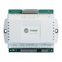
Trane Tracer MP503 User Manual

Trane Tracer MP503
46 pages
To Next Page IconTo Next Page
Page #1 background imageLoading...
Page #1 background image
Installation and
Operation
Tracer MP503
Input/Output Module
CNT-SVX09B-EN
April 2005

Table of Contents

Other manuals for Trane Tracer MP503

Questions and Answers:

Trane Tracer MP503 Specifications

General IconGeneral
ModelTracer MP503
CategoryControl Unit
Input Voltage24 VAC
Enclosure RatingIP20
ApplicationHVAC Systems Control
Communication ProtocolsBACnet MS/TP
Power Supply24 VAC
MountingDIN Rail Mount
TypeProgrammable Controller

Summary

NOTICE

Warnings and Cautions

Explains hazard levels and precautions for safe operation of the equipment.

Important Notes and Symbols

Highlights critical information, procedures, and symbols for user guidance.

Chapter 1 Overview and specifications

Product description

Details the Tracer MP503 I/O module's purpose and capabilities as a field-installed device.

Storage environment

Specifies the required indoor conditions for storing the Tracer MP503 I/O module.

Operating environment

Outlines the temperature and humidity requirements for operating the Tracer MP503 I/O module.

Dimensions

Provides the physical measurements for the plastic-cover and metal-cover models of the module.

Clearances

Details minimum required space around the module for wiring, ventilation, and maintenance.

Power transformer

Specifies the minimum voltage and VA requirements for the module's power transformer.

Agency listing/compliance

Lists certifications and compliance standards met by the Tracer MP503 module.

Chapter 2 General wiring information

Input/output terminal wiring

Outlines requirements for wiring inputs and outputs, including wire type and length limits.

AC-power wiring

Details safe procedures and requirements for connecting AC power to the module.

Communication-link wiring and addressing

Explains wiring and addressing procedures for LonTalk communication links.

Chapter 3 Mounting the module

Location recommendations

Suggests optimal placement for the Tracer MP503 I/O module for installation.

Operating environment requirements

Specifies the environmental conditions for operating the module during installation.

Mounting recommendations

Provides guidelines and best practices for securely mounting the module.

Chapter 4 Applications of the Tracer MP503

Inputs

Describes the four configurable universal inputs and their types (binary, thermistor, mA, Vdc).

Binary inputs

Explains how binary inputs interpret open and closed contacts with 0 Vac and 24 Vac signals.

Thermistor inputs

Details the use of thermistor inputs for temperature measurement with Trane 10kΩ sensors.

0-20 mA inputs

Covers using sensors with 4-20 mA output and the required scaling.

0-10 Vdc inputs

Explains how to use sensors providing a 0-10 Vdc signal and the need for scaling.

Outputs

Describes the form A (SPST) relay outputs and their specifications.

Wiring requirements and options

Illustrates wiring for inputs and a typical binary output.

Chapter 5 Network variable bindings

Overview

Introduces LonTalk protocol for data sharing and the concept of network variable binding.

Network variables

Explains standard network variable types (SNVTs) and the requirement for matching types in bindings.

Binding network variables

Details how to create bindings between LonTalk devices for data exchange.

Tracer MP503 bindings

Discusses the module's role in gathering data and allowing control via bindings.

Receiving data

Lists common network variable inputs (nvis) used for receiving data in MP503 bindings.

Sending data

Lists common network variable outputs (nvo) used for sending data in MP503 bindings.

Examples of network variable bindings

Presents four practical examples of using bindings with the Tracer MP503.

Chapter 6 Status indicators for operation and communication

Tracer MP503 circuit board

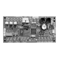
Identifies the location of buttons and LEDs on the module's circuit board.

Service Pin button

Explains the function and uses of the Service Pin button for device management.

Service LED

Explains the red Service LED's indication of normal operation or potential issues.

Status LED

Explains the green Status LED's indication of power status and communication.

LonTalk LED

Explains the yellow LonTalk LED's indication of communication status.

Binary output LEDs

Describes the green LEDs indicating the status of the four binary outputs.

Diagnostics

Lists potential diagnostics, their causes, consequences, and types.

Chapter 7 Troubleshooting

Initial troubleshooting

Provides initial steps to diagnose common problems with the Tracer MP503.

Binary output (relay output) troubleshooting

Guides on troubleshooting issues with binary output functionality and wiring.

Universal input troubleshooting

Guides on troubleshooting incorrect values from universal inputs.

Related product manuals