Chapter 4 Applications of the Tracer MP503
12 CNT-SVX09B-EN
0–20 mA inputs
Many common sensors, such as humidity, pressure, and flow sensors, pro-
vide a 4–20 mA output. You can install any of these sensors, connect it to
an input on the Tracer MP503, and configure that input for 0–20 mA.
IMPORTANT
Because most sensors have 4–20 mA outputs rather than 0–20 mA out-
puts, some scaling is required. The scaling cannot be done at the Tracer
MP503. The Tracer MP503 transmits the raw mA reading.
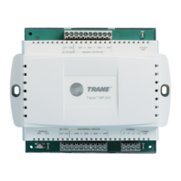
To power these sensors, 24 Vdc is available from the Tracer MP503 circuit
board. See Figure 5 on page 13 for wiring details.
0–10 Vdc inputs
The Tracer MP503 can read a value from a sensor that provides a 0–
10 Vdc signal.
IMPORTANT
If you are using a sensor with a smaller range (such as 2–10 Vdc or 6–
9 Vdc), some scaling is required. The scaling cannot be done at the
Tracer MP503. The Tracer MP503 transmits the raw voltage reading.
To power these sensors, 24 Vdc is available from the Tracer MP503 circuit
board. See Figure 5 on page 13 for wiring details.
Outputs
The binary outputs are form A (SPST) relay outputs. These relays switch
24 Vac; they are not dry contacts. A pilot relay is required for any applica-
tion requiring dry contacts. Relays connected to the binary outputs on the
module cannot exceed 12 VA or 0.5 A current draw at 24 Vac.
 Loading...
