Chapter 6 Status indicators for operation and communication
26 CNT-SVX09B-EN
Tracer MP503 circuit board
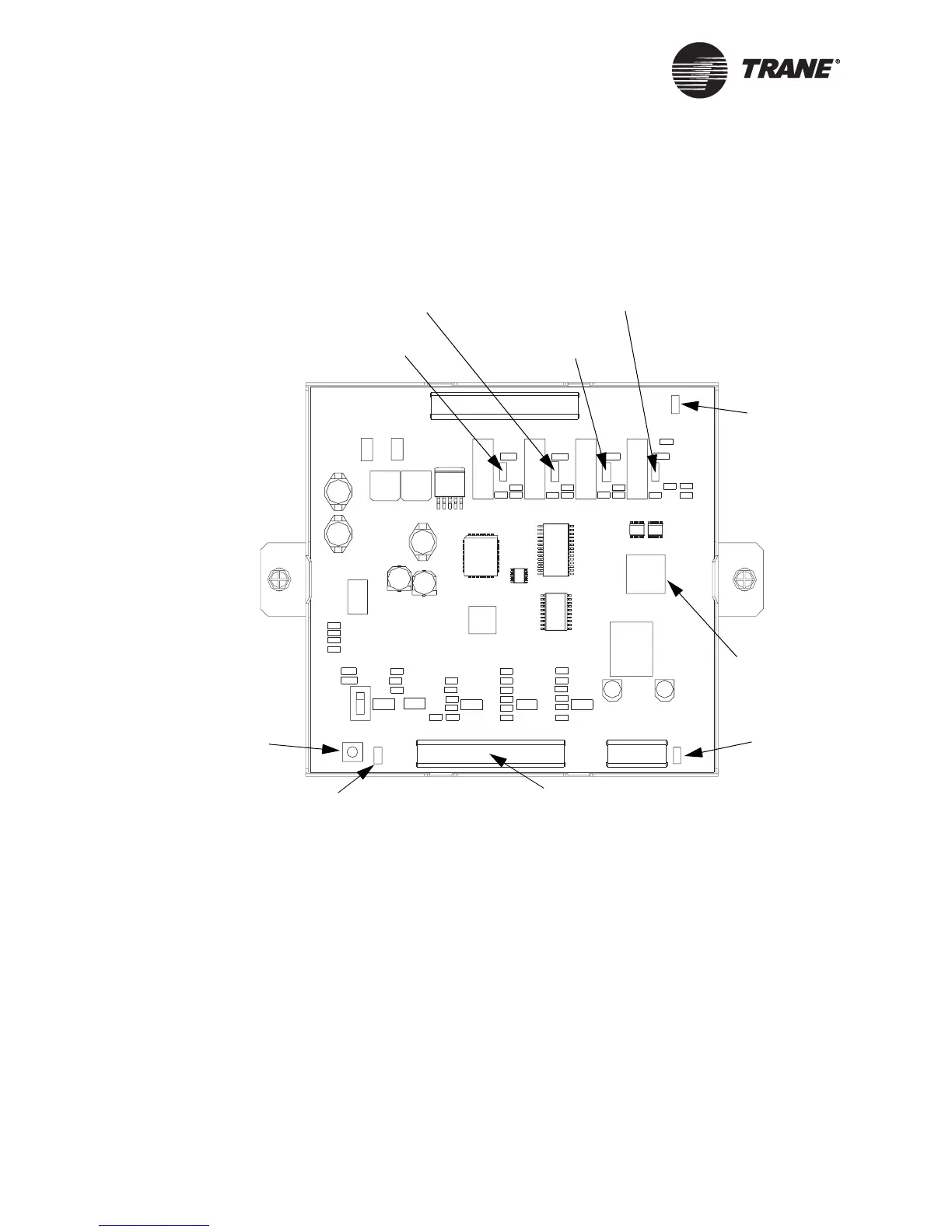
Figure 10 shows the location of the Service Pin button, the Neuron ID
and label, and the LEDs on the Tracer MP503 I/O module circuit board.
Figure 10. Tracer MP503 I/O module circuit board
Service Pin button
The Service Pin button is located as shown in Figure 10. The Service Pin
button is used to:
• Identify a device (see “Identifying a device” in the Rover Operation
and Programming guide, EMTX-SVX01B-EN)
• Add a device to the active group (see “Adding a device” in the Rover
Operation and Programming guide)
• Verify PCMCIA communications (see “Verifying PCMCIA communi-
cations” in the Rover Operation and Programming guide)
• Make the Status (green) LED “wink” to verify that the module is com-
municating on the link (see Table 8 on page 27 and “Setting the auto-
wink option” in the Rover Operation and Programming guide)
LonTalk LED
(yellow)
Neuron ID label
(on back of terminal block)
Service Pin button
Status LED
(green)
Service
LED (red)
Neuron chip
Binary output 1
LED (green)
Binary output 2
LED (green)
Binary output 3
LED (green)
Binary output 4
LED (green)