Chapter 6 Status indicators for operation and communication
28 CNT-SVX09B-EN
LonTalk LED
The yellow LonTalk LED (see Figure 10 on page 26) indicates the commu-
nications status of the module. See Table 9.
Binary output LEDs
Four green LEDs on the Tracer MP503 circuit board indicate the status of
the four binary outputs. The location of each LED is shown in Figure 10
on page 26. Table 10 shows the LED number for each binary output.
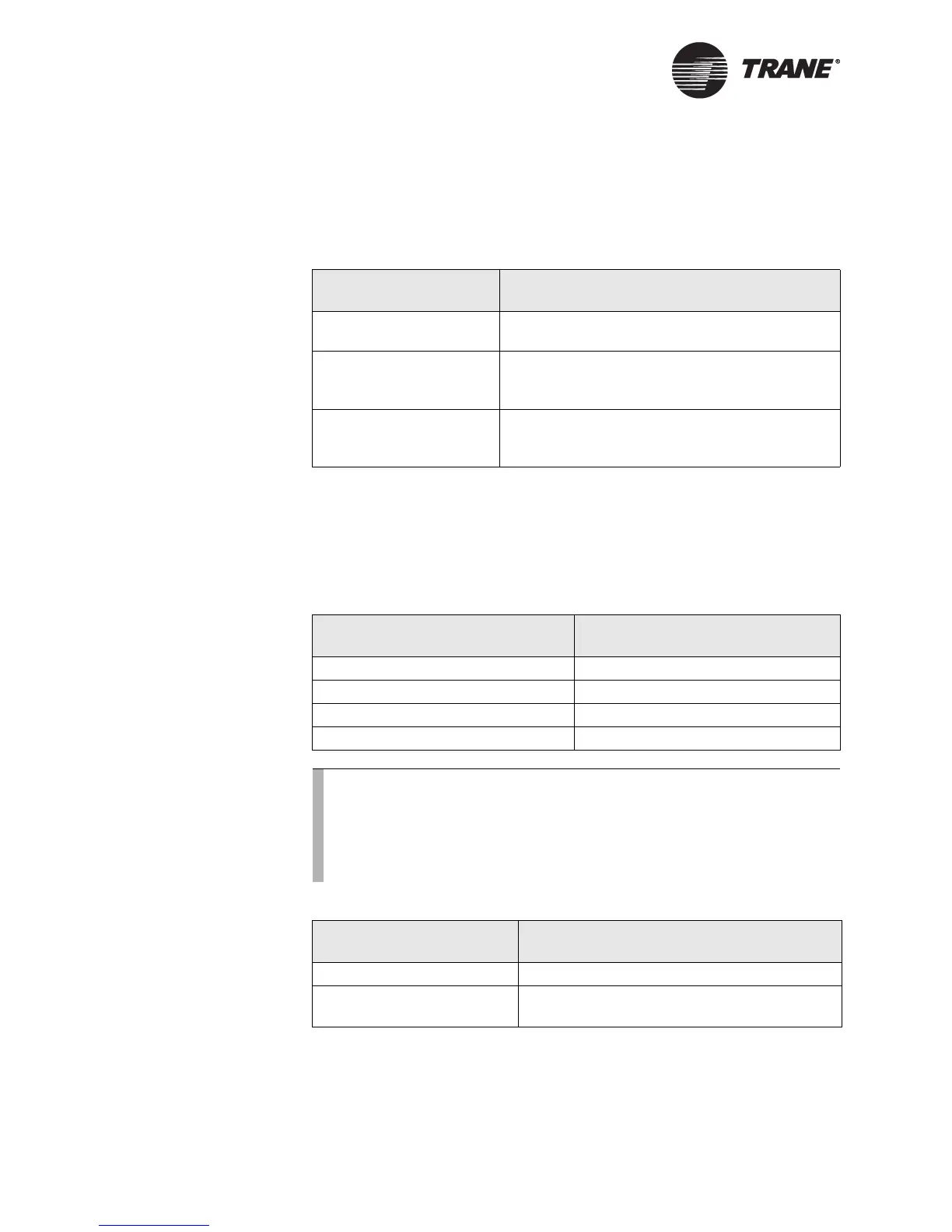
Table 9. Yellow LonTalk LED
LED activity Explanation
LED is off continuously. The module is not detecting any communication
(normal for stand-alone applications).
LED blinks. The module detects communication (normal for
communicating applications, including data
sharing).
LED is on continuously. Abnormal condition. This condition often indi-
cates that external noise is affecting the Tracer
MP503.
Table 10. LED numbers for binary output LEDs
Binary output LED number
1CR8
2CR9
3 CR10
4 CR11
Note:
Each binary output LED reflects the status of the output relay on the
circuit board. It may or may not reflect the status of the equipment
the binary output is controlling. Field wiring determines whether or
not the state of the binary output LED also applies to status of the
end device. Table 11 describes the LED states.
Table 11. Binary output LEDs
LED activity Explanation
LED is on continuously. The relay output is energized.
LED is off continuously. The relay output is de-energized or there is no
power to the board.