5
Installer’s Guide
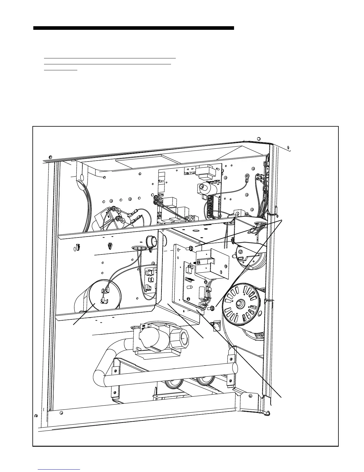
3c. 2/4YC** and 4DC** Units
230 Volt 2/4YC** and 4DC** units with Compres-
sor Start Kit, 460 volt 2/4YC*3060A4, & 460 volt
4YCZ6 units
1. Remove the Control Module from the Universal Bracket (2
machine screws).
2. Then, align the two holes in the ControlModule with the
two clearance holes in the Start Kit bracket.
Figure 5. 230 Volt 2/4YC** and 4DC** units with Compressor Start Kit,
460 volt 2/4YC*3060A4, & 460 volt 4YCZ6 units
3. Mount the Control module to the Start Kit bracket with the
two (2) machine metal screws you removed from the
Universal Bracket. See Figure 5.
Continue with step 4, Mounting the Liquid Line Sensor, page 7.
Compressor
Start Kit
Start Kit
Bracket
Mount Control Module
to Start Kit Bracket
Using Two Sheetmetal
Screws
Control
Module
460v Trans-
former is
mounted in
place of Start
Kit for 460 Volt
2/4YC*3060A4
& 460 Volt
4YCZ6 units
 Loading...


