Do you have a question about the Trane BAYRLAY004A and is the answer not in the manual?
The economizer is a multi-damper design connecting to unit low voltage supply through wire leads.
Economizer installation requires the prior installation of an air filter rack.
BAYRLAY004A relay accessory kit is required when the economizer is installed in WC* models.
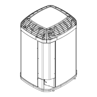
Refer to Figure 2 on page 3 to identify the economizer kit contents.
Report damage to the transportation company and missing parts to the supplier immediately.
Disconnect power before servicing to prevent electrical shock or death.
Lock out unit disconnects to prevent injury or death from electrical shock or contact with moving parts.
Do not remove economizer actuator end covers to prevent injury from spring release.
Use care during insertion to avoid damaging the foil-faced insulation.
Remove the unit economizer/filter access panel, coil, blower, and electrical control box access panels.
The filter frame must be installed prior to economizer installation.
Apply two gaskets to the horizontal economizer mounting flanges.
Set economizer over return air opening, aligning notches with existing screws.
Slide economizer under top lip, aligning notches with screws, and clear bottom screws.
Drill holes and drive screws to secure the top flange of the economizer to the unit.
Drill holes and drive screws to secure the sides of the economizer to the unit.
Mount the Mixed Air sensor to the partition using screws and route wires.
Apply a gasket to the Rain Hood flanges.
Place the Rain Hood over the horizontal return air opening and attach with screws.
Route the main wiring harness to the Mixed Air sensor and to the Control Box.
Connect the two Mixed Air Sensor wires to the mating pigtail wires.
Complete wiring in the Control Box per the diagram and secure all wires.
BAYRLAY004A relay accessory kit is required for WC* heat pump models.
Attach the return duct to the economizer.
Power the economizer and run the checkout procedure, adjusting controller settings.
Reinstall the unit Coil access panel, Blower access panel, and Control Box access panel.
Diagram showing wiring connections for TC*/YC* economizer models.
Diagram showing wiring connections for WC* economizer models, including relay kit.
Procedure to check motor operation for full open, closed, and spring return positions.
Procedure and chart for single enthalpy changeover set point verification.
Detailed steps for checking enthalpy sensor and motor response.
Location of controls and meter points for enthalpy checkout and troubleshooting.
| Model | BAYRLAY004A |
|---|---|
| Refrigerant | R-410A |
| Voltage | 208/230V |
| Phase | 1 |
| Compressor Type | Scroll |
| Product Type | Air Conditioner |
| Cooling Capacity | 4 Tons |
| Weight | 220 lbs |