SS-APG010C-EN
5
Line Sizing, Routing, and Component Selection
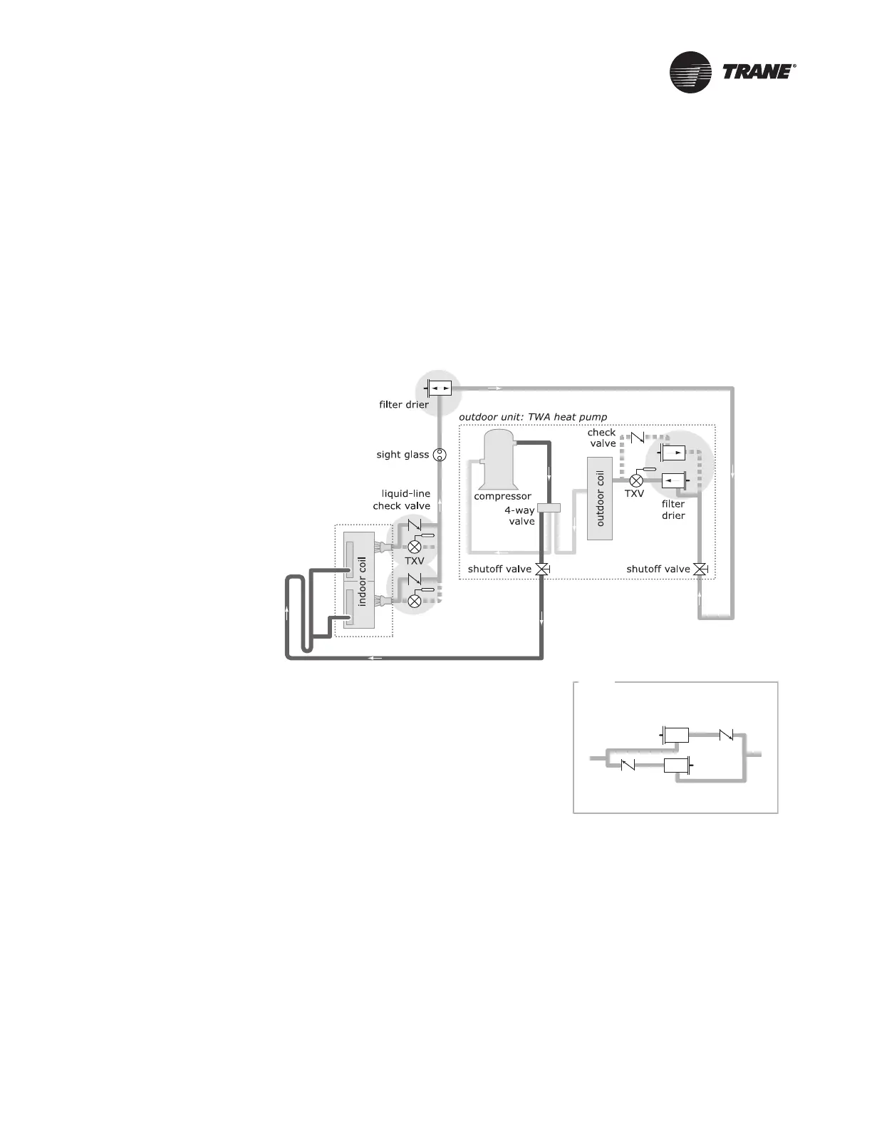
Figure 5 illustrates an example of a (4) TTA/TWA blower coil split system component arrangement.
Use it to determine the proper, relative sequence of the components in the refrigerant lines that
connect the (4) TTA/TWA outdoor unit to the blower coil. Refer to “Refrigerant Piping Examples,”
p. 12, for more detailed schematics of evaporator piping when a single-circuited blower coil is
piped to a single-circuited outdoor unit; when a dual-circuited blower coil is piped to two outdoor
units; or when a dual-circuited blower coil is piped to a single-circuited outdoor unit. All new (4)
TTA/TWA units and BCHC/BCVC units are R-410A products, and all the selected components
installed in the field must also be rated for use with R-410A.
Figure 5. Placement of liquid-line check valves in TWA heat-pump applications when paired
with a BCHC/BCVC blower coil (single circuit shown in heating mode)
Liquid Lines
Line Sizing
Properly sizing the liquid line is critical to a reliable split system application. Table 3, p. 16, shows
the recommended liquid-line sizing for each (4) TTA/TWA model based on its nominal capacity.
Using the preselected tube diameter will maximize the operating envelope and is the line size
around which the installation literature charging charts were generated. Increasing the line size will
not increase the allowable line length.
BCHC/BCVS unit
see INSET
INSET
Heat pump liquid line filters
check valve
check valve