Do you have a question about the Trane BCVC and is the answer not in the manual?
Provides context for the manual and lists previous versions.
Highlights safety precautions and potential hazards.
Emphasizes environmental responsibility regarding refrigerant use.
Defines frequently used HVAC acronyms and abbreviations.
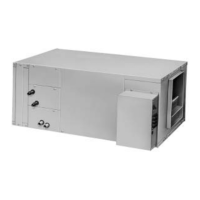
Describes the design and components of blower coil units.
Explains how to interpret model numbers for unit options.
Guidelines for inspecting and handling delivered unit components.
Advice on storing units properly at the jobsite to prevent damage.
Instructions for safely lifting and positioning the unit.
Guidelines for selecting an appropriate installation location.
Detailed dimensions and weight data for horizontal blower coil units.
Detailed dimensions and weight data for vertical blower coil units.
Dimensions and weights for angle filter and mixing box accessories.
Dimensions and weights for bottom or top access filter box options.
Dimensions and weights for electric heat components.
Dimensions and weights for steam coil boxes and connections.
Specifications for hydronic and DX coil connection sizes.
Dimensions and details for basic and deluxe piping packages.
Guidelines for proper ductwork connection to the unit.
Instructions for installing condensate drain piping and traps.
Details on sweat connections for water coils and piping practices.
Guidelines for brazing piping components to prevent damage.
Instructions for DX coil piping, including liquid and suction lines.
Detailed steps for field installation of evaporator piping.
Locating and using unit wiring diagrams for connections.
Installer's responsibility for providing unit power supply wiring.
Describes unit connection points based on control options.
Guidelines for proper electrical grounding to avoid noise issues.
Formulas and tables for calculating electrical circuit requirements.
Table detailing motor specifications, including FLA and IRA.
Step-by-step instructions for installing horizontal blower coil units.
Specific steps for hanging horizontal units with threaded rods.
Instructions for installing vertical blower coil units on the floor.
Procedure for rotating hydronic heating coils for connection changes.
Installation steps for the mixing box accessory.
Detailed steps for attaching the mixing box and installing linkage.
Procedure for attaching linkage components to the mixing box.
Guidelines for installing controllers and zone sensors on walls.
Step-by-step instructions for installing zone sensor modules.
Guidelines for wiring Tracer ZN controllers for communication.
Wiring Tracer ZN controllers directly to the board for service communication.
Steps to follow for starting up the unit after installation.
Overview of Tracer ZN controller communication capabilities.
Wiring Tracer ZN units for Tracer Summit building management systems.
A comprehensive checklist before initiating unit startup.
Checks for unit location adequacy and clearances.
Verifying unit placement, skid removal, and isolator mounting.
Verifying fan, motor, sheaves, belt tension, and rotation.
Ensuring ductwork is complete, secure, and conforms to codes.
Verifying drain piping, water connections, and leak checks.
Checking electrical connections for tightness and verifying voltage/amperage.
Ensuring all unit access panels are in place and secured.
Describes available control options for blower coil units.
Details the control interface and its components for thermostat control.
Information on Tracer ZN010, ZN510, and ZN520 controllers.
Description of the Tracer ZN010 as a stand-alone controller.
Details on ZN510/ZN520 for stand-alone or ICS operation.
Overview of Rover service software for configuring Tracer controllers.
Summary of inputs and outputs for Tracer ZN controllers.
Summary of control functions available for Tracer ZN controllers.
Shows which end devices are available with each controller type.
Describes the operational sequence of Tracer ZN controllers.
Steps followed when 24 VAC power is initially applied to the controller.
Details the different operating modes for Tracer ZN controllers.
Identifies the four ways to control controller occupancy.
How the unit operates when in occupied mode.
How the unit operates when in unoccupied mode.
Operation for ZN510/ZN520 in occupied standby mode.
How to place the controller into occupied bypass mode.
Operation of Tracer ZN controllers with supply fan control via Tracer Summit.
How the controller manages cooling capacity based on setpoints.
How the economizer provides cooling when outdoor conditions are favorable.
Controller behavior with DX cooling, avoiding simultaneous economizer use.
Function to raise discharge air temperature when it falls below a limit.
How the controller manages heating capacity based on setpoints.
How the economizer damper is used for ventilation and cooling.
How the controller manages dehumidification using cooling and reheat.
Describes fan speed selections and configurations.
How the fan speed switch controls fan operation.
Fan mode sequences for Tracer ZN010 and ZN510 controllers.
Fan mode sequences for Tracer ZN520 controllers.
Summary of fan configurations for ZN520 in heating and cooling.
How 2-speed fans operate with selected speeds and valve cycling.
Fan operation during occupied and standby modes.
How Tracer ZN520 cycles the fan in unoccupied mode.
The 30-second delay after heating output turns off to dissipate residual heat.
How fan motors start on high speed for torque.
Describes fan behavior in occupied heating modes for ZN520.
Summary of fan modes for ZN010 and ZN510 in heating and cooling.
Lists valid operating ranges and default setpoints for ZN010/ZN510.
Configuration options for enabling or disabling the local fan switch.
Summary of fan operation based on mode and speed settings.
How Tracer ZN controllers manage changeover using EWT sampling.
How the controller samples EWT to verify correct water temperature for modes.
Table relating unit modes to required water temperatures for changeover.
How Tracer ZN controllers manage electric heat stages.
How the economizer damper is used as a cooling source.
Table showing economizer damper position based on outdoor temperature.
How the controller manages dehumidification using cooling and reheat.
Using LonWorks technology for controller data sharing.
Describes the functions of binary inputs on Tracer ZN controllers.
Configuration and effect of the low temperature detection input.
Configuration and effect of the condensate overflow detection input.
Using occupancy sensors with Tracer ZN controllers.
Using fan status input with ZN520 controllers.
Summary of binary input configurations and controller responses.
Describes the functions of analog inputs on Tracer ZN controllers.
Describes the functions of binary outputs on Tracer ZN controllers.
Details the function, range, and availability of analog inputs.
Details the configuration of binary outputs for various functions.
Describes zone sensor inputs: temperature, setpoint, fan mode, and buttons.
How zone sensors measure space temperature using thermistors.
Using thumbwheels for setpoint adjustment on zone sensors.
Selections available on the fan mode switch.
Providing a local setpoint using a 1kW adjustment.
How the zone sensor fan switch provides fan request signals.
Using buttons for occupied bypass mode and canceling overrides.
Using the RJ-11 jack for communication via Rover service tool.
Summary of zone sensor wiring connections to TB1.
Graph showing resistance vs. temperature for common sensors.
Routine tasks for maintaining unit performance and longevity.
Instructions for inspecting, cleaning, or replacing air filters.
Information on fan bearing lubrication and maintenance.
Guidelines for inspecting fan motors for vibration or temperature.
Steps for aligning fan and motor sheaves for proper operation.
Checking and adjusting fan wheel, bearing, and sheave set screws.
How to check and adjust fan belt tension for optimal life.
Procedures for cleaning and inspecting coils.
General data for fans, filters, and mixing boxes.
Recommended maximum gpm for piping packages to prevent erosion/noise.
General data for hydronic, DX, and steam coils.
Data related to motor and sheave selections for unit drives.
Step-by-step procedure for cleaning various types of coils.
Procedure for draining coils to prevent freeze-up.
Recommended maintenance schedules for monthly, semi-annual, and annual tasks.
Tasks to perform monthly to keep the unit running efficiently.
Tasks to perform semi-annually for unit maintenance.
Tasks to perform annually for unit maintenance and checks.
Explains the meaning of red, green, and yellow LEDs on the controller.
Indicates controller operation status or failure.
Indicates if the controller is powered on.
Indicates controller communication status.
Procedure to verify output and end device operation.
Six methods to reset unit diagnostics.
Sequence for testing outputs on ZN010/ZN510 controllers.
Sequence for testing outputs on ZN520 controllers.
How the controller senses, records, and reports diagnostics.
Controller's automatic function to restore unit after low temp diagnostic.
Using BAS to reset diagnostics in Tracer ZN controllers.
Using Rover service tool to reset diagnostics in Tracer ZN520.
Devices that can communicate alarm reset to clear diagnostics.
How cycling the fan switch resets diagnostics.
Resetting diagnostics via devices that communicate alarm reset.
Table summarizing diagnostics and their effects on unit components.
Table summarizing diagnostics and their effects on unit components.
Probable causes and explanations for fan outputs not energizing.
Probable causes and explanations for valves remaining closed.
Probable causes and explanations for valves remaining open.
Probable causes and explanations for electric heat failure.
Probable causes and explanations for fresh air damper remaining closed.
Probable causes and explanations for fresh air damper remaining open.
More causes and explanations for valves remaining closed.
Causes for DX or electric outputs failing to energize.
Wiring diagram for a two-pipe BCXB unit with a Tracer ZN510 controller.
Wiring diagram for a four-pipe BCXB unit with Tracer ZN510.
Wiring diagram for a four-pipe BCXB unit with Tracer ZN510 (cont.).
Wiring diagram for a four-pipe BCXB unit with Tracer ZN520.
Wiring diagram for a four-pipe BCXB unit with Tracer ZN520 (cont.).
Wiring diagram for a four-pipe BCXB unit with Tracer ZN520 (cont. 2).
Wiring diagram for a four-pipe BCXB unit with Tracer ZN520 (cont. 3).
Wiring diagram for a four-pipe BCXB unit with Tracer ZN520 (cont. 4).
Wiring diagram for a four-pipe BCXB unit with a Control Interface.
Wiring diagram for a four-pipe BCXB unit with Control Interface (cont.).
Wiring diagram for BCXB with DX coil and Tracer ZN520 controller.
Wiring diagram for BCXB with DX coil and Tracer ZN520 controller (cont.).
| Mounting | Direct Drive |
|---|---|
| Model | BCVC |
| Brand | Trane |
| Voltage | 115/208-230V |
| Application | Residential/Commercial HVAC Systems |