Do you have a question about the Trane P0V0 Series and is the answer not in the manual?
Warns of severe injury or death from high voltage. Requires proper procedures.
Emphasizes proper grounding for safety and equipment protection.
Safety precautions for working with live electrical components.
Caution against connecting line voltage to GFCI circuits.
Alert about potential injury from sharp edges on equipment.
Notice regarding potential exposure to chemicals like lead.
Lists the standard features of the modular blowers.
Details available accessories for the modular blower units.
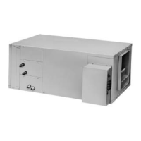
Identifies key components of the modular blower.
Guide to unpacking and inspecting the unit upon receipt.
Recommendations for selecting an appropriate installation site.
Standards for installing ductwork according to NFPA and local codes.
Information on the variable speed motor and airflow adjustments.
Instructions for field wiring, NEC compliance, and low voltage separation.
Importance of installing an air filter to protect components.
Advice on selecting and installing a compatible thermostat.
Steps for unit operation checks and performance adjustments.
Guidelines for periodic maintenance and servicing.
Instructions for removing the front panel for access.
Guidance on installing the blower horizontally in specific locations.
Diagrams illustrating supply duct connection methods.
Configurations and guidelines for return duct connections.
Information on filter types, sizes, and installation requirements.
General notes on making electrical connections and grounding.
Diagrams for field wiring with various thermostat types and heat pumps.
Wiring instructions for communicating systems and controls.
Displays indicating system mode, demand, and airflow status.
Reference for understanding IMBC status and error codes.
Procedures for viewing, clearing, and resetting fault codes.
Initial diagnostic steps and troubleshooting for fault code 01.
Steps to diagnose and fix fault code 06 due to reversed polarity.
Steps to diagnose and fix fault code 06 due to faulty grounding.
Troubleshooting steps for fault code 12 related to the onboard fuse.
Troubleshooting steps for fault code 13 concerning motor HP/ID mismatch.
Troubleshooting steps for fault code 14 regarding Personality Module issues.
Troubleshooting steps for fault code 15 related to corrupted PM or IMBC data.
Troubleshooting steps for fault code 17 indicating no blower motor signal.
Troubleshooting steps for fault code 18 regarding IMBC send message failure.
Specific diagnostic procedures for the serial motor.
Describes timing for EAC and HUM relays during blower operation.
Explains the operational sequence for single-stage cooling mode.
Explains the operational sequence for two-stage cooling mode.
Explains the operational sequence for single-stage heat pump mode.
Explains the operational sequence for two-stage heat pump mode.
Annual inspection checklist for the blower installation.
Guidelines for filter maintenance (cleaning or replacement).
Information on blower motor lubrication and recommended cleaning.
Importance of maintaining condensate drains for proper function.