P0V0
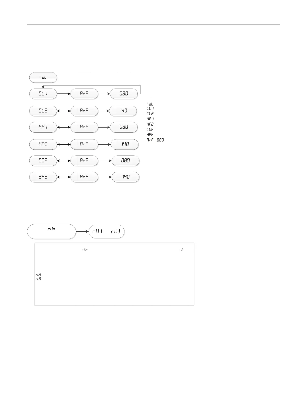
Examples of System Status
= Idle, no demand for cooling, hea!ng, or fan
= Demand for 1
st
stage cooling
= Demand for 2
nd
stage cooling
= Demand for 1
st
stage heat pump
= Demand for 2
nd
stage heat pump
= Demand for con!nuous fan
= Demand for outdoor unit defrost
/ = Calculated airflow is 800 CFM.
Airflow display is rounded down to the nearest 10 cfm
NOTES:
(1) The menu status displayed is solely dependent on the input of 24VAC
that is applied to the low voltage terminal strip.
(2) The status will alternate between the system mode and the airflow
request every 2 seconds.
(3) If an error occurs, an E*.* will al
ternately flash with the system mode
and airflow request.
(4)
Some units will show demand airflow while others will show calculated airflow.
Calculated airflow will gradually ramp up and may take ~1-2 minutes to stabilize.
Example
Calculated CFM
Example
Airflow
Run Test Mode
–
Run Test Mode:
To enter Run Test Mode, scroll to using the Menu key, then push the op!on key. The LED will flash three
!mes, then begin the test.
To exit the test mode, momentarily push the Menu key, cycle power to the
call for capacity or fan.
Sequence of Run Test Mode
– Turns the circula!ng blower on 1st stage compressor speed for 30 seconds
– Turns the circula!ng blower on 2nd stage compressor speed for 30 seconds
The above sequence will repeat two more !mes unless the Run Test Mode is exited, see above
Important: The Run Test Mode does not bring the outdoor unit on. It is designed to allow the technician to
observe each mode to ensure the IMBC, circula!ng blower are performing as intended. The run test
for the blower will take approximately 70 seconds to begin.
Note: During run test mode, depressing the option key will allow the user to hold (HLD) that test
sequence if measurements want to be taken. The exception is RU3 (ignitor).
thermostat
modular blower, or make a valid
 Loading...