CVHE-SVN04M-EN
23
Figure 11. Vane actuator level on interstage
Figure 12. Vane actuator operator mechanism
WWAARRNNIINNGG
RReeffrriiggeerraanntt MMaayy BBee UUnnddeerr PPoossiittiivvee
PPrreessssuurree!!
FFaaiilluurree ttoo ffoollllooww iinnssttrruuccttiioonnss bbeellooww ccoouulldd
rreessuulltt iinn aann eexxpplloossiioonn wwhhiicchh ccoouulldd rreessuulltt iinn
ddeeaatthh oorr sseerriioouuss iinnjjuurryy oorr eeqquuiippmmeenntt ddaammaaggee..
SSyysstteemm ccoonnttaaiinnss rreeffrriiggeerraanntt aanndd mmaayy bbee uunnddeerr
ppoossiittiivvee pprreessssuurree;; ssyysstteemm mmaayy aallssoo ccoonnttaaiinn ooiill..
RReeccoovveerr rreeffrriiggeerraanntt ttoo rreelliieevvee pprreessssuurree bbeeffoorree
ooppeenniinngg tthhee ssyysstteemm.. SSeeee uunniitt nnaammeeppllaattee ffoorr
rreeffrriiggeerraanntt ttyyppee.. DDoo nnoott uussee nnoonn--aapppprroovveedd
rreeffrriiggeerraannttss,, rreeffrriiggeerraanntt ssuubbssttiittuutteess,, oorr nnoonn--
aapppprroovveedd rreeffrriiggeerraanntt aaddddiittiivveess..
2. Disconnect all external vent lines, motor cooling
supply and drain lines, and oil supply and drain
lines which are connected to the compressor and
compressor motor. Sand all paint off the points
where cuts are to be made. Use a tubing cutter to
ensure that cuts are smooth and square. Figure 13,
p. 23 and Figure 14, p. 23 illustrate these lines.
Couplings will be used to reconnect the lines when
reassembling the chiller. Cap open lines to prevent
entry of foreign material.
NNoottee:: Cover all open connections to avoid
prolonged exposure of oil to humid air.
Remove oil if a chiller is kept in a
disassembled condition for an extended time.
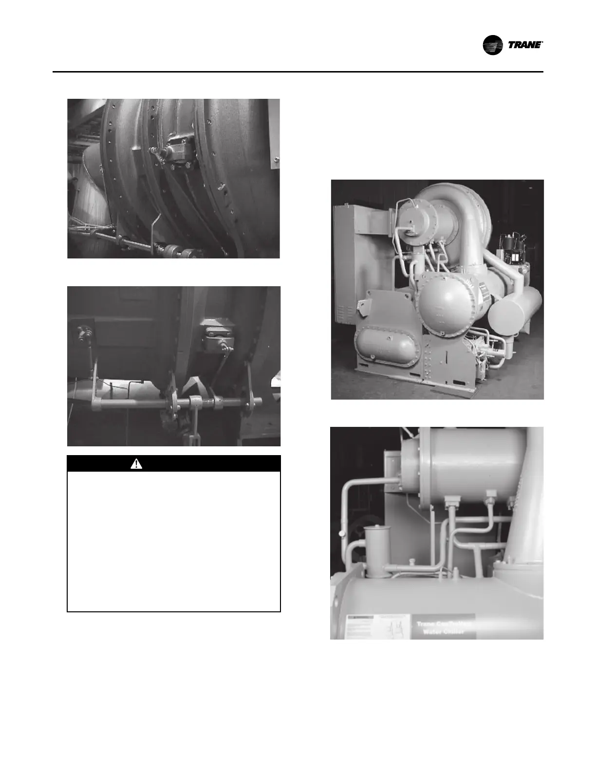
Figure 13. Lubrication system supply, drain, and
vent lines
Figure 14. Lubrication system motor cooling lines
3. Remove the control panel if necessary. Also,
disconnect and remove the unit mounted starter, if
so equipped. See “Control Panel Removal,” p. 27
for instructions.
DDiissaasssseemmbbllyy