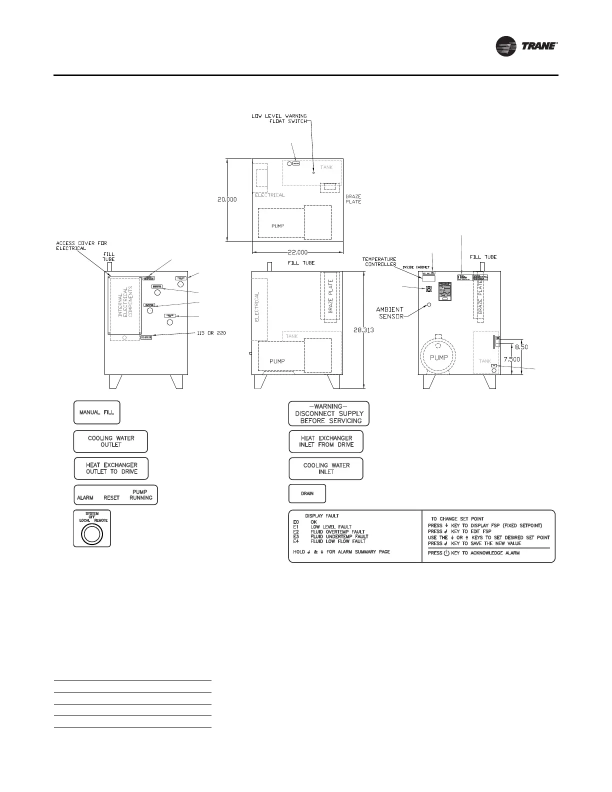
Figure 14. Heat exchanger layout diagram (dimensions in inches)
(a)
(a)Material courtesy of DIMPLEX Thermal Solutions.
1. 2.
3. 4.
5. 6.
7. 8.
9. 10.
Plumbing
AFDK-SVU01C-EN 29
Installation
1. Ensure the unit is placed on a flat, level, hard surface in
a location that allows adequate room for servicing per
local codes. The weight of both water-cooled heat
exchangers is 350 lb. Attach the assembly to the floor
using the ha
rdware in Table 8.
Table 8. Installation hardware
Hardware Qty
3/8 x 3-in. Lag Screw 4
3/8-in. Fender Washer 4
3/8-in. Anchor 4
2. Connect process fluid lines to the proper fittings. Make
sure that the flow of fluid to and from the unit cannot
be shut off or blocked while the system is in operation.
3. Table 9, p. 30 details the connection
s. Some of the
necessary fittings may be included in the accessory
kits shipped separately from the drive (refer to
“Additional Components,” p. 21).
Note: For NPTE fittings,
use Teflo
n
®
paste
(recommended) or Teflon tape. If using tape,
wrap threads of fitting with two complete wraps
of the Teflon tape. Wrap in clockwise direction
when viewed from the pipe thread end. Do NOT
use Teflon tape or other sealant on JIC portion
of fittings.