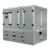
Figure 24. Motor current signature representing surge
AFD Operation
42 AFDK-SVU01C-EN
Interface to Adaptive Frequency Drive
Communications between the chiller control and the AFD
are handled via the Machine Bus (“M-bus”) connected to
the RS-485 AFD Comm Interface module. Signals digitally
sent over the M-bus include start, stop, speed change, and
drive faults.
At start of the compressor motor a signal corresponding to
the startin
g frequency (38 Hz) is sent to the drive.
The digital speed signal is set-up such that the AFD
operates o
ver a 38-60 Hz frequency range.
AFD faults are sent over the M-bus to the UC800 or
DynaView™ controls
for communication on the chiller
display.
High Pressure Cutout—The in
verter accepts a NC HPC
switch
(at terminals 2X1-3 and 2X1-4. In the event of a
chiller high pressure condition, the HPC switch will open
and the drive shall shut down and de-energize the motor.
Output contacts are required to co
ntrol the
load of the oil
pump motor and the cooling circulating pump. The
contacts are normally open, and close when the AFD
energizes the motor.
Note: Unlike locke
d rotor amps associated with
el
ectromechanical starters, the phase currents are
not expected to rise above 85 percent RLA prior to
1.6 seconds following
the sending of the speed
signal, after which they then remain above
85 percent RLA until the compressor motor has
come up to speed.
An “Up-to-Sp
eed” signal must occur before the Maximum
Acceleration Timer times out (plus 15 seconds) or a
MANUAL RESET (MMR) al
arm will occur.
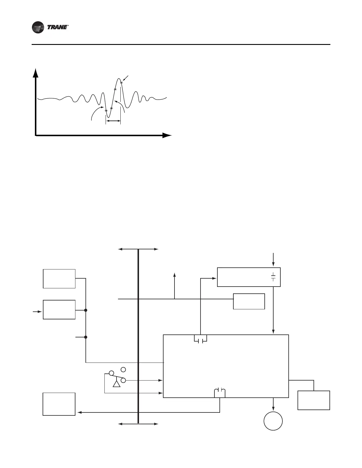
The block diagram (see Figure 25, p. 42) shows the
com
mun
ication of the starter module to Unit Mounted
Inverter Interface controls interconnecting circuits.
The Oil Pump Interlock load is 115 volts ac, 3/4 hp reset.
Figure 25. Chiller control to remote-mounted inverter interface block diagram
Present
Sampled
Value
Previous
Sampled
Value
Rectified
Motor
Current
Transitory
Pressure
Breakdown
Pressure
Rebuilding
1 Surge
Occurrence
Time
AFD
Chiller
Chiller
Control
Power Supply
Oil Pump
Interlock
To other
LLIDs
115/50/60
Power
4-wire
Machine Bus
24 Vdc Power
and Ground
115/50/60
Power
3-phase line
Circuit Breaker
line in with
115 Vac
115 Vac
HPC
24 Vdc Sense
115 Vac
3/4 hp
Adaptive Frequency™ Drive
Motor
AFD
Chiller
Recomm
HPC
24 Vdc
Out
24 Vdc
In
Cooling
Pump