12
4. Assembly and
Installation
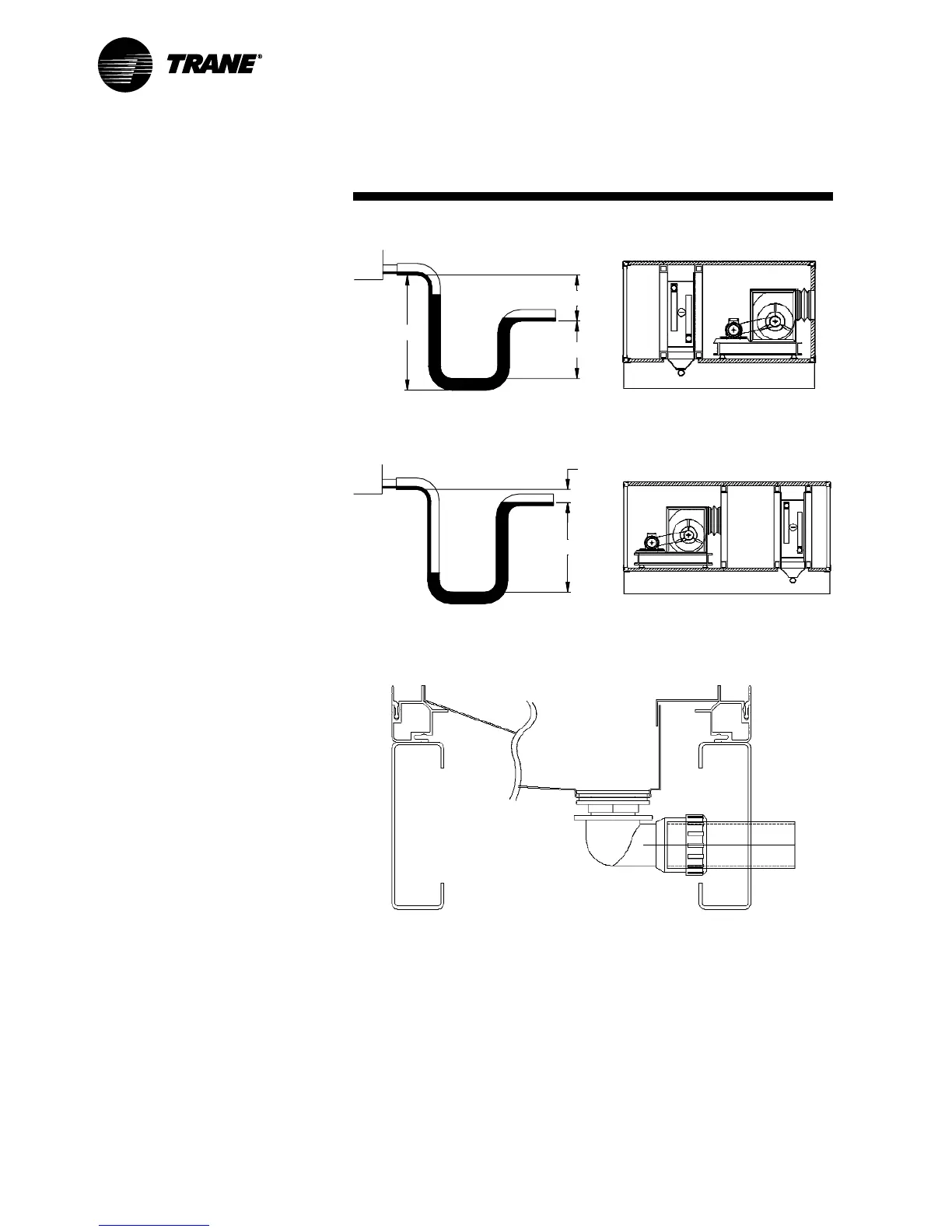
Figure 13 – Negative Pressure Trap (Draw Through)
Figure 14 – Positive Pressure Trap (Blow Through)
Figure Notes:
1. 25 mm for each 250 Pa of maximum
negative static pressure + 25 mm
2. 0.5 x dimension 1
3. Dimensions 1 + 2 + pipe diameter +
insulation
Figure Notes:
1. Minimum of 12 mm
2. 12 mm + maximum total static pressure
Figure 15 – Drip Pans
1
1
2
2
3
4.5 Drip Pans
A UPVC elbow and 1-1/2" [38 mm]
diameter (internal dimension) discharge
pipe is supplied as standard (3.2 mm wall
thickness).
A copper elbow and 35 mm diameter
discharge pipe is available as an option
(1.2 mm wall thickness).
Drip pans (see Figure 15) are not
designed to be walked on.
CLCH-SVX05A-GB