12 WSHP-SVN08B-EN
RETURN-AIR OPENING
FLANGE ON CABINET
RETURN-AIR OPENING
FLANGE ON CABINET
2 X 4 STUD
A
B
Unit Size
09
012
015
018
024
036
A
19 1/4”
(489)
23 1/4”
(591)
27 1/8”
(689)
B
44 1/8”
(1121)
45 1/4”
(1149)
54 5/8”
(1387)
SHEET ROCK
OPENING
TOP VIEW
SIDE VIEW
CABINET
5“
B
4 5/8“
2 1/4“
3 1/2” ±3/8”
3 1/2” ±3/8”
1 1/2” X 2 3/8”
FLOOR
SHEETROCK
SHEETROCK
RETURN AIR
DOOR FRAME
RETURN AIR
DOOR FRAME
1“ X 1” CLOSED
CELL INSULATION
1“ X 1” CLOSED
CELL INSULATION
3 1/2” ±3/8”
1 1/4”
+1/2”/-0”
1 1/4”
+1/2”/-0”
A
1“ X 1” CLOSED
CELL INSULATION
1“ X 1” CLOSED
CELL INSULATION
2“ X 4”
STUD
2“ X 4” STUD
RETURN AIR OPENING
FLANGE ON CABINET
RETURN AIR OPENING
FLANGE ON CABINET
SHEETROCK
SHEETROCK
RETURN AIR
DOOR FLANGE
CABINET
CABINET
Note:
Finished wall and framing should not
touch the unit cabinetry.
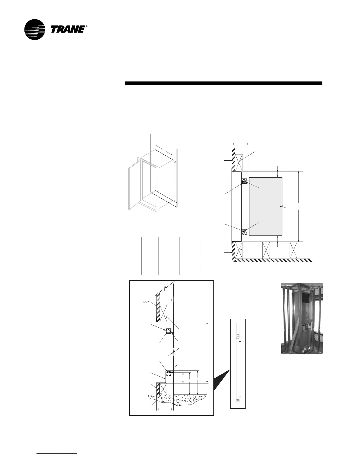
Drywall Installation
Before installing drywall around cabi-
net. Cover the cabinet supply and re-
turn openings with plastic or
cardboard to help prevent dust or con-
struction debris from reaching unit
components. Warranties will be void-
ed if paint or foreign debris is allowed
to contaminate internal unit compo-
nents.
The location of the drywall may be de-
pendent upon the type of return air ac-
cess design.
1 Units that contain a field provided
return air access assembly, contrac-
tor must calculate location of dry-
wall to allow for frame mounting.
Units utilizing Hinged Acoustic
Door Assembly.
1 Locate the side studs a minimum of
1 1/4-inches and a maximum of 1 3/
8-inches from the cabinet to the side
of the stud. This critical dimension,
combined with "distance between
studs" is used to determine the side-
to-side opening for the door, dimen-
sion A. The distances provided in
the table are a "minimum" dimen-
sion. Allow 3 1/2-inches from the
front of the cabinet to the sheet rock
surface, Figure 4 - Top View. Figure
5, mock-up of stud placement.
2 The height of the door assembly
must be positioned to recess the
door 2 1/4-inches from the cabinet’s
return-air opening, Figure 4 - Side
View blow-up.
3 Locate dimensions A and B for sheet
rock opening size. The position of
the sheet rock opening must be cen-
tered side-to-side with the return-air
opening in the cabinet. Ensure the
bottom of the sheet rock opening is
2 1/4-inches below the return-air
opening in the cabinet. This allows
the door recess to rest on the bot-
tom of the sheet rock opening for
proper vertical placement of the
door.
Installation
Figure 4: Drywall installation for hinged acoustic door
4 Place the door frame into the sheet rock opening. A positive seal is critical be-
tween the back of the door frame and the front of the cabinet. Ensure that the
gasket material seals properly. Note: When placing the sheet rock panel, make
certain the opening for the door is centered with the return-air opening in the
cabinet (±1/8").
Figure 5: