EasyManua.ls Logo

Trane Axiom GECE 006 User Manual

Trane Axiom GECE 006
40 pages
To Next Page IconTo Next Page
Page #1 background imageLoading...
Page #1 background image
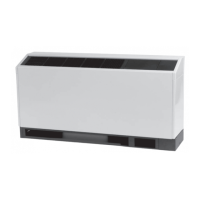
Water Source Heat Pump
Axiom™ High Efficiency Console
0.5 to 1.5 Tons — 50/60 Hz
Installation, Operation, and Maintenance
March 2021
WSHP-SVX11E-EN
Model Numbers:
GECE 006, 009, 012, 015, 018 (60 Hz)
GECE 006, 009, 012, 015 (50 Hz)
SAFETY WARNING
Only qualified personnel should install and service the equipment. The installation, starting up, and servicing of
heating, ventilating, and air-conditioning equipment can be hazardous and requires specific knowledge and training.
Improperly installed, adjusted or altered equipment by an unqualified person could result in death or serious injury.
When working on the equipment, observe all precautions in the literature and on the tags, stickers, and labels that are
attached to the equipment.
Questions and Answers:

Trane Axiom GECE 006 Specifications

General IconGeneral
BrandTrane
ModelAxiom GECE 006
CategoryHeat Pump
LanguageEnglish

Summary

Introduction

Warnings, Cautions, and Notices

Defines the three types of safety advisories: Warning, Caution, and Notice.

Important Environmental Concerns

Discusses the impact of certain chemicals on the ozone layer.

Important Responsible Refrigerant Practices

Outlines Trane's stance on responsible refrigerant handling and regulations.

Personal Protective Equipment (PPE) Required!

Details the mandatory PPE for installation and servicing.

Follow EHS Policies!

Highlights the importance of following Environmental, Health, and Safety policies.

Copyright

States Trane's ownership of the document and rights to revise it.

Trademarks

Mentions that all referenced trademarks belong to their respective owners.

Revision History

Lists updates made to the document, e.g., Electrical Data updates.

Model Number Description

Model Number Breakdown

Details the breakdown and meaning of each digit in the unit model number.

General Information

Jobsite Inspection

Details checks to perform upon unit delivery to ensure no damage.

Jobsite Storage

Provides guidelines for proper unit storage to prevent damage and microbial growth.

Unit Dimensions

Service Clearances

Specifies required clearances around the unit for servicing.

Weights

Unit Weight Data

Provides unit and chassis weight data for various models.

Installation

Hazardous Voltage!

Warns about the danger of high voltage and the need for power disconnection.

Proper Field Wiring and Grounding Required!

Stresses the importance of qualified personnel for wiring and grounding.

Electrical Data

Electrical Specifications

Presents detailed electrical specifications for various unit models.

Pre-Start Checklist

Pre-Start Verification

Lists essential checks before energizing the unit for operation.

Start-Up

Initial Unit Start-up

Provides step-by-step instructions for starting up the unit with a conventional thermostat.

Start-Up Checklist and Log

A checklist for contractors to complete before full system operation.

Operating Pressures

Explains factors affecting refrigerant pressures and provides approximate conditions.

Water Pressure Drop

Explains how to define pressure drop using tables and calculation methods.

Water Volume

Provides water volume data for GEC* units for glycol calculations.

Maintenance

Preventive Maintenance

Offers suggestions for maintaining the unit for proper operation.

Filter sizing

Shows filter sizes for standard and low height units.

Filter Replacement (standard height configuration)

Step-by-step guide for replacing filters in standard height units.

Filter Replacement (low height configuration)

Step-by-step guide for replacing filters in low height units.

Troubleshooting

Deluxe 24V Controls

Explains the use of LEDs on the deluxe 24V control for troubleshooting.

Diagnostic LEDs

Details the meaning of diagnostic LED patterns for controller modes.

Troubleshooting table

Lists common problems, causes, and corrections for unit operation.

Wiring Diagrams

Deluxe 24V controls

Wiring schematic for units with deluxe 24V controls.

Tracer® ZN524

Wiring schematic for units with Tracer® ZN524 controller.

Tracer® UC400-B - 208V-60 Hz - 1pH

Wiring schematic for UC400-B controller units.

Tracer® UC400-B - 208V-60 Hz - 1pH with hot gas reheat

Wiring schematic for UC400-B with hot gas reheat.

Warranty

Standard Warranty

Outlines the terms of the standard parts-only and compressor warranty.

Extended Warranty

Details the optional extended warranty coverage and conditions.

Related product manuals