WSHP-SVX11E-EN 5
Digits 1-3 — Unit Configuration
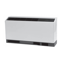
GEC = High Efficiency Console
Digit 4 — Unit Configuration
E
Digits 5-7 — Nominal Capacity
006 = 0.5 Tons
009 = 0.75 Tons
012 = 1 Tons
015 = 1.25 Tons
018 = 1.5 Tons
Digit 8 — Voltage Volts/Hz/
Phase)
0 = 115/60/1
1 = 208/60/1
2 = 230/60/1
6 = 220-240/50/1
7 = 265/60/1
Digit 9 — Heat Exchanger
1 = Copper-Water Coil
2 = Cupro-Nickel Water Coil
Digit 10 — Design Sequence
B
Digit 11 — Refrigeration Circuit
0 = Heating and Cooling Circuit
2 = Heating and Cooling Circuit with Hot
Gas Reheat
Digit 12 — Blower Configuration
1= Standard Blower Motor
Digit 13 — Freeze Protection
A = 20° F Freezestat (Extended Range
Geothermal)
B = 35° F Freezestat
Digit 14 — Open Digit
0 = Open Digit
S = Design Special
Digit 15 — Supply-Air
Arrangement
0 = Standard Supply-Air Arrangement
Digit 16 — Return-Air
Arrangement
0 = Standard Return-Air Arrangement
Digit 17 — Control Types
D = Deluxe 24V Controls
B = Tracer® ZN524 Controls
E = Deluxe 24V Control with
Programmable Thermostat
H = UC400-B
J = UC400-B with Air-Fi® Wireless
Communications
Digit 18 — Tstat/Sensor Location
0 = Wall Mounted Location
1 = Unit Mounted Location with Standard
Entry
2 = Unit Mounted Location with Keylock
Entry
Digit 19 — Fault Sensors
1 = Condensate Overflow Sensor
3 = Condensate Overflow and Filter
Maintenance Timer
6 = Condensate Overflow and Fan Status
J = Condensate Overflow Sensor, Fan
Status and Filter Maintenance Timer
Digit 20 — Temperature Sensor
0 = No Additional Temperature Sensor
1 = Entering Water Sensor
Digit 21 — Open Digit
0 = Open Digit
Digit 22 — Electric Heat
0 = No Electric Heat
2 = Boilerless Control Electric Heat
(minimum)
3 = Boilerless Control Electric Heat
(maximum)
Digit 23 — Unit Mounted
Disconnect
0 = No Unit Mounted Disconnect
A = Power Cord/Receptacle Box
B = Power Cord/Receptacle Box with
Circuit Breaker
C = On/Off Toggle Switch
Digit 24 — Filter Type
0 = No Filter; Chassis Only
1 = 1-inch Throwaway Filter
A = 1-inch MERV 8 Filter
Digit 25 — Acoustic
Arrangement
0 = Enhanced Sound Attenuation
Digit 26 — Factory Configuration
0 = Standard Factory Configuration
(Chassis, Cabinet and Subbase)
1 = Chassis ONLY
2 = Low Height Factory Configuration
(Chassis, Cabinet and Subbase)
3 = Extended Length Factory
Configuration (
Chassis, Cab
inet and
Subbase)
Digit 27 — Paint Color
0 = No Paint Selection Available
1 = Deluxe Beige
2 = Cameo White
3 = Soft Dove
Digit 28 — Outside Air
0 = No Outside Air Option
1 = Outside Air Opening
2 = Motorized Outside Air (2-p
osition)
Digit 29 — Piping Arrangement
L = Left Hand Piping Arrangement
R = Right Hand Piping Arrangement
Digit 30-36 — Does Not Apply to
GEC
0000000 = Digits 30-36 are not applicable
to the GEC product
Model Number Description
 Loading...
