WSHP-SVX11E-EN 31
Maintenance
WARNING
Hazardous Service Procedures!
Failure to follow all precautions in this manual and on
the tags, stickers, and labels could result in death or
serious injury.
Technicians, in order to protect themselves from
potential electrical, mechanical, and chemical hazards,
MUST follow precautions in this manual and on the
tags, stickers, and labels, as well as the following
instructions: Unless specified otherwise, disconnect all
electrical power including remote disconnect and
discharge all energy storing devices such as capacitors
before servicing. Follow proper lockout/tagout
procedures to ensure the power can not be
inadvertently energized. When necessary to work with
live electrical components, have a qualified licensed
electrician or other individual who has been trained in
handling live electrical components perform these
tasks.
Preventive Maintenance
Maintenance on the unit is simplified with the following
preventive suggestions:
Filter maintenance must be perfo
rmed to assure proper
operation of the equipment. Filters should be inspected at
least every three months, and replaced when it is evident
they are dirty. Filter sizing is shown in Table 8, p. 31:
Table 8. Filter sizing
Unit Size
(50/60 Hz) Filter Size (Nominal) inches
006-018 10 x 32 3/8 (std height unit)
006-018 7 ¾ x 30 5/8 (low height unit)
Check the contactors and relays within the control panel at
least once a year. It is good practice to check the tightness
of the various wiring connections within the control panel.
A strainer (60 mesh or greater) mu
st be used on an open
loop system to keep debris from entering the unit heat
exchanger and to ensure a clean system.
For units on well water, it is important to check the
cl
eanlin
ess of the water-to-refrigerant heat exchanger.
Should it become contaminated with dirt and scaling as a
result of bad water, the heat exchanger will have to be back
flushed and cleaned with a chemical that will remove the
scale. This service should be performed by an experienced
service person.
It should be noted that the water quality should be checked
p
eriodically. See Table 9, p. 31.
Table 9. Water quality
Scaling Amount
Calcium and magnesium (total hardness) Less than 350 ppm
Corrosion
pH 7-9.5
Hydrogen Sulfide Less than 1 ppm
Sulfates Less than 25 ppm
Chlorides Less than 125 ppm
Carbon Dioxide Less than 75 ppm
Total dissolved solids (TDS) Less than 1000 ppm
Biological Growth
Iron Bacteria Low
Erosion
Suspended Solids Low
Filter Replacement (standard height
configuration)
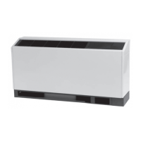
Filter replacement is done at the front return-air opening of
the console unit. No tools are required for the
replacement. The maintenance process is done via a 3-
STEP process:
1. Through the return-air opening, slide filter to the back
of
the consol
e unit.
2. Allow the front edge of the filter to drop to floor level.
3. Pull the filter out
of the front opening.
Note: REVE
RSE the cy
cle to install a new filter.
Filter Replacement (low height
configuration)
Filter replacement is done at the front return-air opening of
the console unit. A slotted screw driver is needed for the
replacement. The maintenance process is done via a 2-
STEP process.
1. Insert screw-driver and depress gril
l tab (2-per grille).
Rotate grille down, an
d lift grille upward to remove
grille. The removal of one grille is required.
2. Slide the filter through the gril
le hole in
the cabinet
front panel.
Note: REVERSE the cy
cle to install a new filter.
 Loading...
