18 OAU-SVX007A-EN
General Information
Overview of Manual
Note: One copy of this document ships inside the control
panel of each unit and is customer property. It must be
retained by the unit’s maintenance personnel.
This booklet describes proper installation, operation, and
maintenance procedures for air cooled systems. By carefully
reviewing the information within this manual and following the
instructions, the risk of improper operation and/or component
damage will be minimized.
It is important that periodic maintenance be performed to help
assure trouble free operation. A maintenance schedule is
provided at the end of this manual. Should equipment failure
occur, contact a qualified service organization with qualified,
experienced HVAC technicians to properly diagnose and
repair this equipment.
Model Number Description
All products are identified by a multiple-character model
number that precisely identifies a particular type of unit. An
explanation of the alphanumeric identification code is provided
(see Model Number chapter). Its use will enable the owner/
operator, installing contractors, and service engineers to
define the operation, specific components, and other options
for any specific unit.
When ordering replacement parts or requesting service, be
sure to refer to the specific model number and serial number
printed on the unit nameplate.
Unit Nameplate
A Mylar
®
unit nameplate is located on the unit’s corner support
next to the control box. It includes the unit model number, serial
number, electrical characteristics, refrigerant charge, as well
as other pertinent unit data.
Compressor Nameplate
The nameplate for the compressors are located on the side of
the compressor.
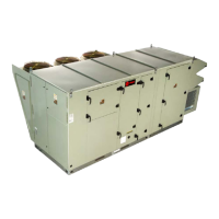
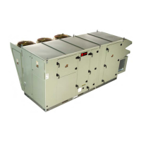
Unit Description
Before shipment, each unit is leak tested, dehydrated, charged
with refrigerant and compressor oil, and run tested for proper
control operation.
The condenser coils are aluminum fin, mechanically bonded to
copper tubing.
Direct-drive, vertical discharge condenser fans are provided
with built-in thermal overload protection.
The Outdoor Air Unit Main Unit Display and ReliaTel™ Control
Module (RTRM) are microelectronic control systems. The
acronym RTRM is extensively throughout this document when
referring to the control system network.
The Main Unit Display and the RTRM are mounted in the Main
Control Panel. The Main Unit Display and RTRM receive
information from sensors and customer binary contacts to
satisfy the applicable request for ventilation, cooling,
dehumidification and heating.
Indoor Fan Failure Input
The Indoor Fan Failure Switch (IFFS) is connected to verify
indoor fan operation.
When there is a call for the indoor fan to be energized, the
differential pressure switch, connected to the Main Unit
Display, must prove airflow within 30 seconds or the Main Unit
Display will shut off all mechanical operations, lock the system
out and send a diagnostic alarm to the Unit Display. The
system will remain locked out until a reset is initiated through
the MCM via the Alarm Reset Function on the Unit Display.
Low Pressure Control ReliaTel Control
This input incorporates the compressor low pressure control
(CLP 1/2) of each refrigeration circuit and can be activated by
opening a field supplied contact installed on the OAUTS.
If this circuit is open before the compressor is started, the
ReliaTel™ control will not allow the affected compressor to
operate. Anytime this circuit is opened for 1 continuous second
during compressor operation, the compressor for that circuit is
immediately turned “Off.” The compressor will not be allowed
to restart for a minimum of 3 minutes should the contacts close.
If four consecutive open conditions occur during the first 3
minutes of operation, the compressor for that circuit will be
locked out, and a manual reset will be required to restart the
compressor.
High Pressure Control ReliaTel Control
The compressor high pressure controls (CHP 1/2/3/4) are
wired in series between the compressor outputs on RTRM1
(CHP 1/2) and RTRM2 (CHP 3/4) and the compressor
contactor coils. If one of the high pressure control switches
opens, the respective RTRM senses a lack of current while
calling for cooling and locks the compressor out.
On dual circuit units, if the high pressure control opens, the
compressor on the affected circuit is locked out. A manual
reset for the affected circuit is required.
Space Temperature/RH Sensor (Optional)
Field installed, wall mounted combination temperature/
humidity sensor (BAYSENS036A) to control space cooling,
heating and dew point.
High Temperature Sensor
The Discharge Air Temperature Sensor (DTC) supplies a
continuous signal to the MCM. Factory setting for Discharge
Air Temperature (DTC) Discharge Air Temperature Setpoint
Maximum (MDTS) is 120°F (range of (80-120°F), the unit will
be shut down, and require a manual restart if Discharge Air
Temperature exceeds MDTS for 10 minutes (adj 10–
25 minutes). If DAT exceeds Discharge Air High Temperature
 Loading...