Start-Up
94 OAU-SVX007A-EN
modulating sections, the outlet gas pressure from main/
regulator valve into the modulating valve is 5-in. WC.
Main On-Off valves in 1/2-in. gas line require 3/32-in. Allen
wrench to adjust outlet gas pressure. Valves in
3/4-in. gas line require flat blade screwdriver to adjust
outlet gas pressure. Following these sequences, inducer
speed will reduce to low speed and will now be speed-
controlled by the heater controller based on gas input to
burners.
With heating command at 100 percent and with a single
split manifold heater installed, the On-Off section of the
heater will require the modulating section to prove ON
before the On-Off section will enable. Inducer speed high
at all times the On-Off section is in ignition sequence or
firing. On-Off section sequence includes a 1-second
ignition pre-purge followed by 4-second ignition trial.
Ignition or flame failure will be followed by 30-second inter-
purge for two ignition retry then 5-minute lockout period if
both retry attempts fail. Correct manifold gas pressure for
On-Off heater section is 3.5-in. WC.
For units including an additional separate On-Off heater,
set heat command output to 49 percent to run modulating
heater startup. When complete with modulating heater
startup, increase heat output command to 100 percent to
start up the second heater.
High Fire and Low Fire Adjustment
To adjust high fire or low fire setting, please refer to EXA
STAR modulating valve document. This document will ship
with all gas heat units.
Failure to Ignite
• On the initial startup, or after unit has been off long
periods of time, the first ignition trial may be
unsuccessful due to need to purge air from manifold at
startup.
• If ignition does not occur on the first trial, the gas and
spark are shut-off by the ignition control and the control
enters an inter-purge period of 15 seconds, during
which the draft inducer continues to run.
• At the end of the inter-purge period, another trial for
ignition will be initiated.
• Control will initiate up to three ignition trials on a call for
heat before lockout of control occurs.
• Control can be brought out of lockout by cycling call for
heat at the main unit display.
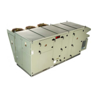
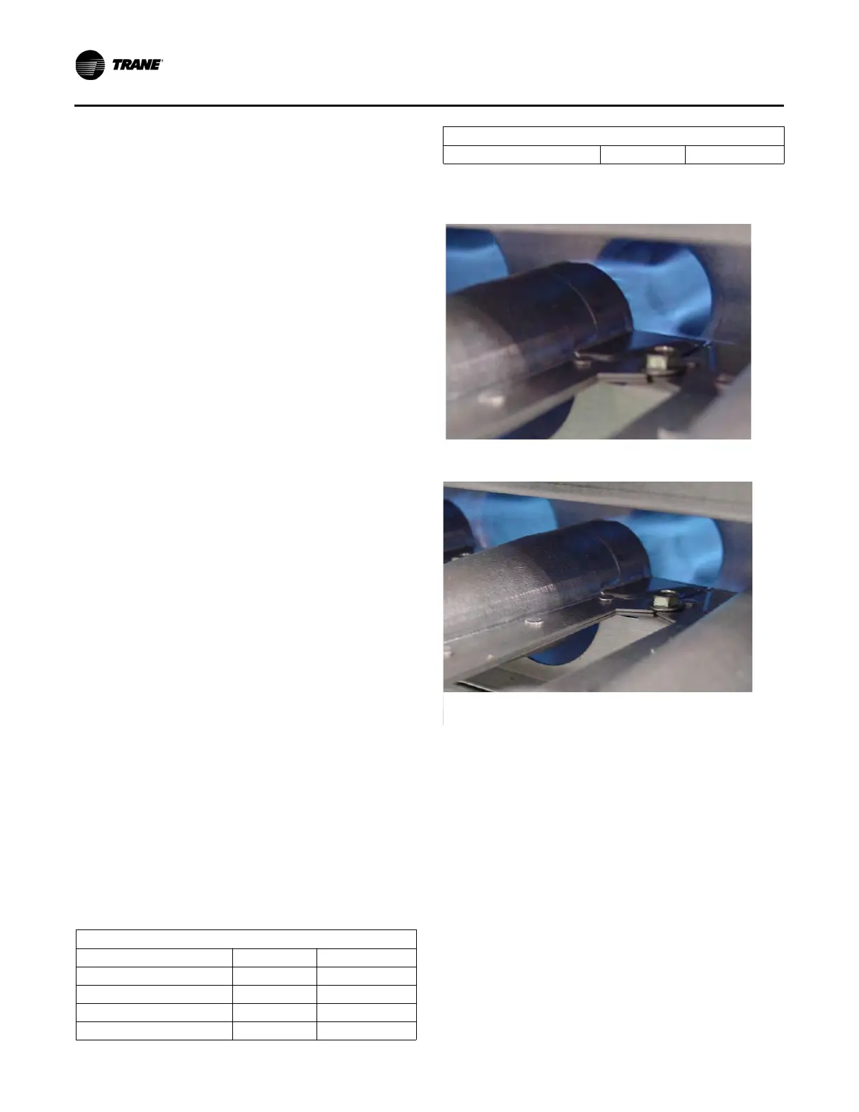
Prior to completing the startup, check the appearance of
the main burner flame. Refer to Figure 143 for flame
characteristics of properly adjusted natural gas systems.
Main Burner Flame
• The burner flame should be predominately blue in color
and well defined and centered at the tube entry as
shown in Figure 143 above. Distorted flame or yellow
tipping of natural gas flame, or a long yellow flame on
propane, may be caused by lint and dirt accumulation
inside burner or at burner ports, at air inlet between
burner and manifold pipe, or debris in the main burner
orifice. Soft brush or vacuum clean affected areas.
• Poorly defined, substantially yellow flames, or flames
that appear lazy, indicate poor air supply to burners or
excessive burner input. Verify gas supply type and
manifold pressure with rating plate.
• Poor air supply can be caused by obstructions or
blockage in heat exchanger tubes or vent discharge
pipe. Inspect and clean as necessary to eliminate
blockage. Vacuum any dirt or loose debris. Clean heat
exchanger tubes with stiff brush. Poor flame
characteristics can also be caused by flue gas
Pressure Settings
Fuel Type NG LP
Unit Inlet (in.) 7-14 10-14
Modulating Valve Inlet (in.) 5.0 10.0
Manifold (in.) 3.5 8.0
Low Fire (in.) 0.4 0.8
High Fire (in.) 3.5 8.0
Figure 143. Flame characteristics of properly-adjusted
natural gas systems
Pressure Settings
Burner flame at startup: 1.2-in. WC manifold pressure draft
inducer—high speed
Burner flame at high fire: 3.5-in. WC manifold pressure draft
inducer—high speed
 Loading...