58 RT-SVX36G-EN
Installation
Note: Do not rely on the gas train shutoff valves to isolate the unit while conducting gas pressure/
leak test. These valves are not designed to withstand pressures in excess of 14" w.c. or 0.5
psig.
Connecting the Gas Supply Line to the Furnace Gas Train
Follow the steps below to complete the installation between the supply gas line and the furnace.
Refer to Figure 24 through Figure 27 for the appropriate gas train configuration.
1. Connect the supply gas piping using a “ground-joint” type union to the furnace gas train and
check for leaks.
2. Adjust the inlet supply pressure to the recommended 7" to 14" w.c. parameter for natural gas.
3. Ensure that the piping is adequately supported to avoid gas train stress.
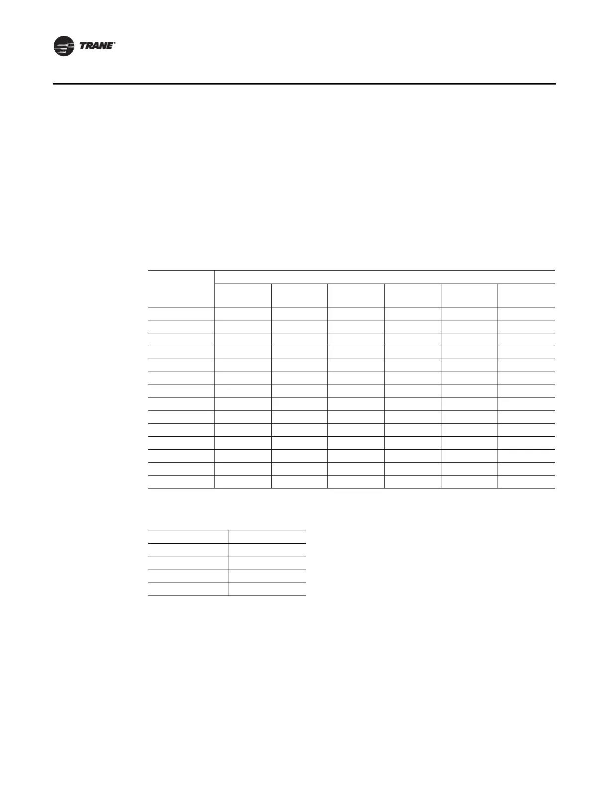
Table 16. Sizing Natural Gas Pipe Mains and Branches
Gas Input (Cubic Feet/Hour)*
Gas Supply
Pipe Run (ft)
1-1/4"
Pipe
1-1/2"
Pipe
2"
Pipe
2-1/2"
Pipe
3"
Pipe
4"
Pipe
10 1050 1600 3050 4800 8500 17500
20 730 1100 2100 3300 5900 12000
30 590 890 1650 2700 4700 9700
40 500 760 1450 2300 4100 8300
50 440 670 1270 2000 3600 7400
60 400 610 1150 1850 3250 6800
70 370 560 1050 1700 3000 6200
80 350 530 990 1600 2800 5800
90 320 490 930 1500 2600 5400
100 305 460 870 1400 2500 5100
125 275 410 780 1250 2200 4500
150 250 380 710 1130 2000 4100
175 225 350 650 1050 1850 3800
200 210 320 610 980 1700 3500
* Table is based on a specific gravity of 0.60. Use Ta b le 1 7 for the specific gravity of the local gas supply.
Table 17. Specific Gravity Multipliers
Specific Gravity Multiplier
0.50 1.10
0.55 1.04
0.60 1.00
0.65 0.96
 Loading...


