27
Installation (Continued)
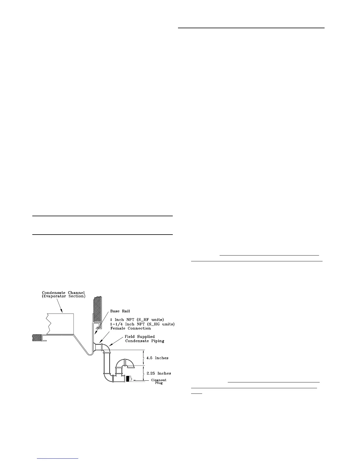
Condensate Drain Connections
Each S_HF unit is provided with two or six 1" evaporator
condensate drain connections (one on each side of the
unit). Each S_HG unit is provided with two or six 1-1/4"
evaporator drain connections (one on each side of the
unit.)
Due to the size of these units, all condensate drain con-
nection must be connected to the evaporator drain con-
nections. Refer to the appropriate illustration in Figure 3-2
for the location of these drain connections.
A condensate trap must be installed due to the drain con-
nection being on the "negative pressure" side of the fan.
Install the P-Traps at the unit using the guidelines in Figure
3-6.
Pitch the drain lines at least 1/2 inch for every 10 feet of
horizontal run to assure proper condensate flow. Do not al-
low the horizontal run to sag causing a possible double-
trap condition which could result in condensate backup
due to "air lock".
Units with Gas Furnace
Units equipped with a gas furnace have a 3/4" CPVC drain
connection stubbed out through the vertical support in the
gas heat section. It is extremely important that the conden-
sate be piped to a proper drain. Refer to the appropriate il-
lustration in Figure 3-2 for the location of the drain connec-
tion.
Note: Units equipped with an optional modulating
gas furnace will likely operate in a condensing
mode part of the time.
An additional 1-1/4" non-connectable water drain is lo-
cated in the base rail within the heating section.
Ensure that all condensate drain line installations comply
with applicable building and waste disposal codes.
Figure 3-6
Condensate Trap Installation
Shipping Fasteners
Removing Compressor Assembly Shipping Hardware
(20 through 60 Ton)
Each manifolded compressor assembly is rigidly bolted to
a mounting rail assembly. The rail assembly sets on four
(4) rubber isolators. The assembly is held in place by two
shipping braces that secure each compressor rail assem-
bly to the unit's base rail. To locate and remove the ship-
ping hardware, refer to Figure 3-7 and the following proce-
dure.
1. Remove the four anchor bolts (2 front and 2 rear), used
to secure the shipping brace to the unit's base rail (two
assemblies on 40 through 60 Ton units).
2. Remove the three self-tapping screws that secure each
shipping brace to the compressor mounting rails.
3. Remove and discard the two 30-1/2" long shipping
braces for each assembly.
4. Do not remove the shipping bracket located on top of
the compressors.
5. Ensure that the compressor rail assembly is free to
move on the rubber isolators.
Removing Compressor Assembly Shipping Hardware
(70 & 105 Ton)
Each manifolded compressor assembly is rigidly bolted to
a mounting rail assembly. The rail assembly sets on six (6)
rubber isolators. The assembly is held in place by four (4)
shipping "Tiedown" bolts. To remove the shipping hard-
ware, follow the procedures below:
1. At each "Tiedown" location (2 front and 2 rear), remove
and discard the tiedown bolt and the slotted shipping
spacer located between the compressor rails and the
unit base rail illustrated in Figure 3-7B, "Tiedown Bolt"
detail.
2. Remove the bolt in each rubber isolator and the slotted
shipping spacer located between the compressor rails
and the unit base rail illustrated in Figure 3-7B, "Isolator
Bolt" detail.
Reinstall the bolts at the same location by
screwing them into the base rail two to three turns only.
3. Ensure that the compressor rail assembly is free to
move on the rubber isolators.
Removing Compressor Assembly Shipping Hardware
(115 and 130 Ton)
Each manifolded compressor assembly is rigidly bolted to
a mounting rail assembly. The rail assembly sets on eight
(8) rubber isolators. The assembly is held in place by six
(6) "Tiedown Bolts". To remove the shipping hardware, fol-
low the procedure below:
1. At each "Tiedown" location (6), remove and discard the
tiedown bolt and the slotted shipping spacer located
between the compressor rails and the unit base rail il-
lustrated in Figure 3-7C, "Tiedown Bolt" detail.
2. Remove the bolt in each rubber isolator and the slotted
shipping spacer located between the compressor rails
and the unit base rail illustrated in Figure 3-7C, "Isola-
tor Bolt" detail.
Reinstall the bolts at the same location
by screwing them into the base rail two to three turns
only.
3. Ensure that the compressor rail assembly is free to
move on the rubber isolators.

 Loading...


