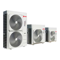
Picco R32 Inverter air/water heat pumps with axial fan
37
TECHNICAL CHARACTERISTICS Unit
Picco R32 - PSEC
140 250 260
Cooling
Cooling capacity (1) kW 29,4 35,7 47,4 53,1
Power input (1) kW 10,20 12,2 15,8 18,1
E.E.R. (1) W/W 2,88 2,93 3,00 2,93
Cooling capacity (2) kW 37,3 54,2 64,8 66,5
Power input (2) kW 9,47 13,5 15,8 17,0
E.E.R. (2) W/W 3,94 4,01 4,10 3,91
SEER (5) W/W 3,96 4,20 4,46 4,49
Water ow (1) L/s 1,41 1,71 2,27 2,54
Heang capacity (3) kW 40,5 49,8 61,7 67,1
Power input (3) kW 10,40 12,7 15,5 16,8
C.O.P. (3) W/W 3,89 3,92 3,98 3,99
Heang capacity(4) kW 40,8 50,1 59,9 66,8
Power input (4) kW 13,1 15,9 18,8 20,8
C.O.P. (4) W/W 3,11 3,15 3,19 3,21
Heang capacity (12) kW 38,8 48,8 56,1 62,8
Power input (12) kW 14,8 18,6 22,2 24,3
C.O.P. 12) 2,62 2,62 2,53 2,58
SCOP (6) W/W 3,83 3,89 3,72 3,69
Water ow (4) L/s 1,95 2,40 2,87 3,20
Energy eciency - water 35°C / 55°C Class A++ / A+ A++ / A+ A+ / A+ A+ / A+
Compressor
Type Scroll DC Inverter
Quanty 1 2 2 2
Refrigerant oil (type) FW68S FW68S FW68S FW68S
Refrigerant oil (quanty) mL 1900 3800 3800 3800
Refrigerant circuits 1 1 1 1
Refrigerant
Type R32
Refrigerant circuits (7) kg 6,5 9,5 11,7 12,0
Refrigerant quanty in tonnes of CO2 equivalent (7) ton 4,4 6,4 7,9 8,1
Design pressure (high/low) heat pump mode bar 46 / 27,6
Design pressure (high/low) chiller mode bar 46 / 27,6
fan
Type EC
Quanty 1
Nominal power (1) kW 1,95 1,95 3,1 3,1
Maximum power input kW 1,95 1,95 3,1 3,1
Maximum current input A 4,8 4,8 4,8 4,8
Nominal air ow L/s 4368 5431 6417 5547
Internal heat
exchanger
Internal heat exchanger type Plates / BPHE
N° internal heat exchanger 1 1 1 1
Water content L 3,05 3,54 4,27 5,12
circuit
Useful head (1) (**) kPa 437 429 405 394
Useful head (4) (**) kPa 411 387 360 341
Water content of the hydronic circuit L 7 7 8 9
Maximum pressure hydronic kit (safety valve seng) bar 6 6 6 6
Grooved water connecons inch
1" 1/2 (DN
40)
1" 1/2 (DN
40)
1" 1/2 (DN
40)
1" 1/2 (DN
40)
Minimum water volume (8) L 286 389 490 522
Nominal pump power (1) kW 2,20 2,20 2,20 2,20
Maximum pump power input kW 2,20 2,20 2,20 2,20
Maximum pump current input A 4,15 4,15 4,15 4,15
Noise
Sound power level Lw (9) dB(A) 77 83 84 84
Sound power level Lw SL conguraon (9) dB(A) 76 82 83 83
Sound power level Lw SSL conguraon(9) dB(A) 75 81 82 82
Electrical
data
Power supply 400V/3P+N+T/50Hz
Maximum power input kW 24 33 39 43
Maximum current input A 38 52 62 68
Max. power input with anfreeze kit kW 25 34 40 43
Max. current input with anfreeze kit A 40 54 64 70
 Loading...