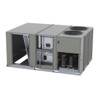
Field Installed Assembly and Installation
ACC-SVN261A-EN 7
Optional Sensors
If the optional sensors for humidity and temperature monitoring
are needed (FIAENTH001* and FIAENTH002*), install them
using the instructions provided in those kits.
Install Duct Blockoff Plate
(Downflow Units only)
Important: If power exhaust or barometric relief accessory
kits are installed along with an economizer, do
not install the duct blockoff plate.
See below figure.
• For units without a smoke detector, install 15 with flange 16
poi
nting down.
• For units with a smoke detector, remove knockout 17, and
th
en install 15 with flange 16 pointing up.
Figure 5. Installing the duct blockoff plate
Without smoke detector With smoke detector
15
16
17
16
15
Install Economizer into the
Rooftop Unit
See Figure 1, p. 6, Figure 6, p. 7, and Figure 8, p. 8.
1. Lift the assembled economizer unit into position.
2. Fit the upper left hand corner arou
nd the channel in the
cabinet post.
3. Pivot the economizer into the opening in the cabinet.
4. Lift the economizer and panel assembly to align the upper
scr
ew holes.
5. Secure the top left and top right with screws.
6. Pull out on the bottom of the economizer and secure it with
th
e bottom three screws 23.
7. Remove the filter access panel.
8. Position 3 inside the filter sectio
n. 3 will slip over the three
screws.
9. Align the holes in the plate with the holes in the panel.
10. Secure the bottom right with a screw 22.
11. Install the bottom blockoff 21 and secure it with three
screws 23.
12. Using field supplied silicone, apply sealant around
e
conomizer hood 24.
Figure 6. Selling and seams
Symbio™ Wiring Connections
Using the supplied harness connect PPF87 to the actuator
connector. Route harness to fresh air options module located
in the return section and connect to FAOM-J11. After
installation is complete, Symbio™ 700 UC unit configuration
will need to be updated to reflected installed option.
Factory Installed Economizer
Set-Up
This section covers setup of economizer units that have been
installed in the rooftop unit at the factory.
Downflow Configuration
WARNING
Hazardous Voltage!
Failure to disconnect power before servicing could
result in death or serious injury.
Disconnect all electric pow
er, including remote
disconnects before servicing. Follow proper lockout/
tagout procedures to ensure the power can not be
inadvertently energized. Verify that no power is present
with a voltmeter.
See Figure 7, p. 8, and Figure 8, p. 8.
1. Remove filter access panel.
2. Remove the screw that holds bottom blockoff 21 in place,
a
nd then remove bottom blockoff 21 from its shipping
location.
3. Remove the bottom three screws fro
m the economizer
panel 23.
4. Pull the economizer assembly out into operating position.
 Loading...