This document provides installation instructions for Electric Heaters designed for Precedent™ Packaged Rooftop Units, ranging from 6 to 25 tons, with standard efficiency. It covers the installation, inspection, and safety guidelines for these electric heaters.
Function Description:
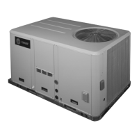
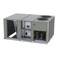
These electric heaters are designed to provide supplemental heating for Precedent™ Packaged Rooftop Units. They integrate into the existing rooftop unit to deliver heated air, enhancing comfort in commercial and residential applications. The heaters are available in various kW ratings and stages, allowing for flexible application based on heating requirements. The installation process involves integrating the heater element assembly and its control panel into the rooftop unit's vestibule and heat sections.
Usage Features:
The electric heaters are intended for use with specific Precedent™ rooftop unit models, as detailed in the "Used With" tables. The installation process is outlined for two main tonnage ranges: 6 to 12.5 tons and 15 to 25 tons (cooling only) and 12.5 to 25 tons (heat pump).
For 6 to 12.5 ton units, the installation involves:
- Unpacking and inspecting all kit components for shipping damage and verifying the heater nameplate model number against electrical data tables.
- Removing the heater compartment access panel and unit control box access panel.
- Removing insulation and a removable panel from the vestibule panel to expose the opening for the heater.
- Checking the vestibule panel opening for burrs or slivers that could damage heater elements.
- Sliding the electric heater element assembly along guide rails until it is fully seated, ensuring the "BOTTOM" stamp on the mounting panel is correctly oriented.
- Securing the heater element assembly with screws.
- Sliding the electric heater control panel/access door assembly inward until it engages with retaining clips and securing it with screws.
- Installing hinged door stops by loosening existing screws, positioning the stops flush against the center post, and re-securing.
- Wiring control voltage to the indoor options module using the supplied harness, routing wires from the heater assembly to the main control box.
- Verifying that heating elements are not damaged, pinched, or short-circuited to each other, the heater frame, or the equipment cabinet. This involves testing each heater element with an ohmmeter to ensure electrical isolation from the cabinet and ground.
- Checking the tightness of all terminal connections, clamps, and screws.
- Installing magnets into the door.
- Closing the electric heater control panel access door, replacing the heat section access panel, and unit control box access panel.
- Replacing the horizontal supply cover, ensuring the gasketing is intact and creates a watertight seal.
- Scratching out the square on the unit nameplate indicating the installed heater model.
For 15 to 25 ton cooling only and 12.5 to 25 ton heat pump units, the installation involves:
- Removing the heat section access panel.
- Removing screws that secure the bottom through-the-base electrical (TBUE) panel.
- Removing the bulkhead post to gain access to the heat compartment.
- Identifying the top of each heater element using the airflow direction label on the terminal plate, ensuring the airflow arrow points down.
- For dual heaters, adjoining the two heaters with screws, installing a ring bushing into the faceplate, and routing Heater 2 wires through the bushing and to Heater 2 terminals. For single heaters, installing a plastic cap.
- Attaching the two-piece wire chase together with screws and then attaching the wire chase to the heater assembly, ensuring the wire harness is inside the chase.
- Connecting the wire harness to the correct terminals on Heater 2 and Heater 1 (referencing the wiring schematic on the hinged door inside the kit).
- Trimming away the heater opening perforation in the insulation and clipping sheet metal tabs to remove the removable portion of the sheet metal.
- Sliding the heater assembly into the unit, engaging side brackets between guide rails, and ensuring the wire harness is clear.
- Securing the heater assembly to the heater vestibule with screws.
- Installing the magnet bracket at the top of the heat section with screws.
- Installing the heater control panel in the unit with screws.
- Installing the heater terminal block plate to the unit base rail and heater control panel.
- Connecting the heater element wire harness(es) to the contactors and from the terminal block to the heater fuse blocks and main power fuse block.
- Routing control wires from Fuse 6-8 up through the top opening in the heater into the main control box and connecting to HTB1.
- Connecting the control harness to connectors on the electric heat contactors and routing it to the main control box and indoor options module.
- Installing the bulkhead post.
- Installing the lower TBUE panel to the base.
- Installing the heater door assembly, mounting the bracket on the bottom rail, and ensuring schematic labels face inward and warning labels face out.
- Installing screws to secure the heat section access panel.
- Scratching out the square on the unit nameplate indicating the installed heater model.
Maintenance Features:
The manual emphasizes several safety and maintenance-related practices:
- Safety Warnings: Highlights the importance of qualified personnel for installation and servicing, proper field wiring and grounding, and the use of Personal Protective Equipment (PPE) to prevent death or serious injury from electrical, mechanical, and chemical hazards.
- Capacitor Discharge: Instructs technicians to disconnect all electric power and discharge all motor start/run capacitors before servicing, verifying discharge with a CAT III or IV voltmeter.
- Copper Conductors Only: Specifies that only copper conductors should be used to prevent equipment damage.
- EHS Policies: All Trane personnel must follow company Environmental, Health and Safety (EHS) policies, and non-Trane personnel should follow local regulations.
- Refrigerant Practices: Stresses responsible refrigerant handling, noting that all technicians handling refrigerants must be certified according to local rules and adhere to federal, state, and municipal requirements.
- Pre-Power Verification: Before applying power, technicians must verify that heating elements are not damaged, pinched, or short-circuited and that all terminal connections, clamps, and screws are tight.
- Post-Operation Tightening: All electrical connections should be tightened after the equipment has been in operation and components have reached operating temperature.
- Gasketing Integrity: When replacing the horizontal supply cover, ensure gasketing is not torn or missing and makes a watertight seal.
The document also includes a "Temperature Rise Data" table, which provides air temperature rise values for different kW stages and airflow rates, along with a formula to calculate temperature rise at different airflows. This data is crucial for understanding the heater's performance and ensuring it meets design specifications.