40
RT-SVX075C-EN
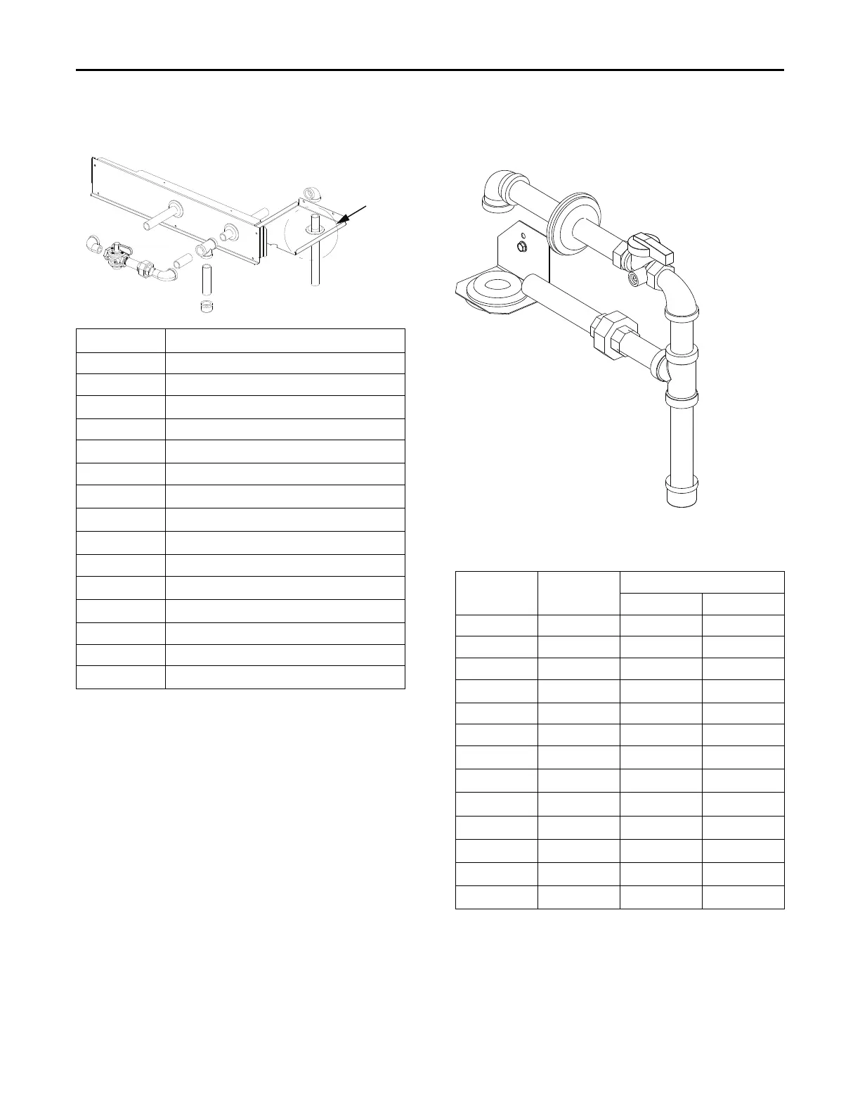
Figure 61. Through-the-base gas pipe assembly for
YHJ(180-300)*
See Detail A
A
B
C
D
E
M
L
K
J
I
H
F
N
O
G
Component Description
A Grommet
B Grommet
C
Pipe Fitting (3/4-in. x 8 1/2-in.)
D 90° Elbow
E
Support Plate
F Tee
G
Pipe Fitting (3/4-in. x 4-in.)
H
Cap
I
Pipe Fitting (3/4-in. x 2 1/2-in.)
J 90° Street Elbow
K
Pipe Union
L
Pipe Fitting (3/4-in. x 2 1/2-in.)
M Gas Shut-off Valve
N 90° Street Elbow
O
Pipe Fitting (3/4-in. x 6 1/2-in.)
Figure 62. Through-the-base gas pipe assemblies for
YHJ(072-150)*
A
B
C
D
A
E
F
G
H
J
K
L
M
I
1/2-in. and 3/4-in., Gas Pipe Connection
Table 6. Through-the-base gas pipe assembly
components for YHJ(072-150)* (inch)
Component Description
Connection Size
1/2 inch 3/4 inch
A Grommets ½ ¾
B TBUG bracket - -
C 90° Elbow ½ ¾
D
Pipe fitting
½ x 7¼ ¾ x 6½
E Gas ball valve ½ ¾
F Street elbow ½ ¾
G
Pipe fitting
½ x 2 ½ ¾ x 2¼
H
Tee pipe
½ ¾
I
Pipe fitting
½ x 4 ¾ x 4
J
Pipe cap
½ ¾
K
Pipe fitting
½ x 2 ¾ ¾ x 2
L
Pipe union
½ ¾
M
Pipe fitting
½ x 4 ½ ¾ x 5¼
Note: All modulating gas models use 3/4-inch gas piping.
For detailed through-the-base gas installation instructions,
refer to the Through-the-Base Gas Piping 3 to 25 Tons
Gas/Electric Packaged Units Installation Instructions (ACC-
SVN17*-EN) provided with through-the-base gas
installation kit.
Installation

 Loading...