RT-SVX075C-EN
39
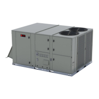
Figure 59. Wireless communication interface -
horizontal
Note: Cable ties must be removed to allow the cable to
extend to the horizontal mounting location.
Main Electrical Power
Requirements
WARNING
Hazardous Voltage w/Capacitors!
Failure to disconnect power and discharge capacitors
before servicing could result in death or serious
injury.
Disconnect all electric power, including remote
disconnects and discharge all motor start/run
capacitors before servicing. Follow proper lockout/
tagout procedures to ensure the power cannot be
inadvertently energized. For variable frequency drives
or other energy storing components provided by
Trane or others, refer to the appropriate
manufacturer’s literature for allowable waiting periods
for discharge of capacitors. Verify with a CAT III or IV
voltmeter rated per NFPA 70E that all capacitors have
discharged.
WARNING
Proper Field Wiring and Grounding
Required!
Failure to follow code could result in death or serious
injury.
All field wiring MUST be performed by qualified
personnel. Improperly installed and grounded field
wiring poses FIRE and ELECTROCUTION hazards. To
avoid these hazards, you MUST follow requirements
for field wiring installation and grounding as
described in NEC and your local/state/national
electrical codes.
1. Verify that the power supply complies with the unit
nameplate specifications.
2. Inspect all control panel components and tighten any
loose connections.
3. Connect properly sized and protected power supply
wiring to a field-supplied/installed disconnect switch
and to the main power terminal block (HTB1) in the unit
control panel.
4. Install proper grounding wires to an earth ground.
Through-the-Base Gas
Installation
Important: All phases of this installation must comply with
national, state, and local codes. In absence of
local codes, the installation must conform with
American National Standard-Z223.1a-
National Fuel Gas Code Latest Revision.
Note: For complete Gas Heat User information, Operation,
Start-up, Shutdown and Maintenance refer to “Gas
Heat Operation and Maintenance,” p. 68.
1. Remove the access panel for the heat section on the
front of the unit for field connections.
2. The gas piping assembly ships inside this section and
includes the shut-off valve, a pressure tap for testing,
and the necessary unions for field connection. For
through the base access, remove the factory-provided
cap from the base pan opening. See Figure 60, p. 39
and Figure 61, p. 40.
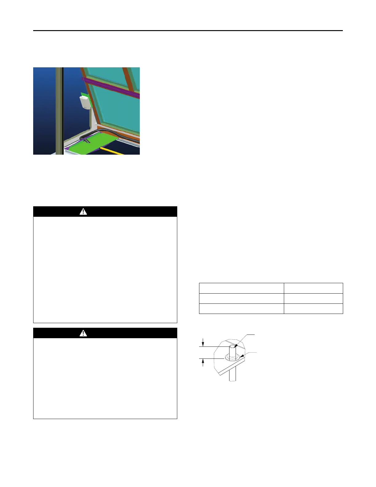
3. Route field piping through this hole to the dimension
shown in Table 5, p. 39.
4. Place the assembly through the cabinet opening shown
in Figure 61, p. 40 and make the union connection to
the field piping and to the gas train.
Table 5. Through-the-base gas piping dimension
Model
Dimension A (inch)
YHJ(072-150)***(0,A) (L, M, H)
4 5/8
YHJ(180-300)***(0,A)(L, M, H)
1 3/16
Figure 60. Through-the-base gas pipe height
A
Customer Gas Supply Pipe
Grommet
DETAIL A
Installation

 Loading...