100
SS-SVX11K-EN
WWAARRNNIINNGG
LLiivvee EElleeccttrriiccaall CCoommppoonneennttss!!
FFaaiilluurree ttoo ffoollllooww aallll eelleeccttrriiccaall ssaaffeettyy pprreeccaauuttiioonnss
wwhheenn eexxppoosseedd ttoo lliivvee eelleeccttrriiccaall ccoommppoonneennttss ccoouulldd
rreessuulltt iinn ddeeaatthh oorr sseerriioouuss iinnjjuurryy..
WWhheenn iitt iiss nneecceessssaarryy ttoo wwoorrkk wwiitthh lliivvee eelleeccttrriiccaall
ccoommppoonneennttss,, hhaavvee aa qquuaalliiffiieedd lliicceennsseedd eelleeccttrriicciiaann
oorr ootthheerr iinnddiivviidduuaall wwhhoo hhaass bbeeeenn pprrooppeerrllyy ttrraaiinneedd
iinn hhaannddlliinngg lliivvee eelleeccttrriiccaall ccoommppoonneennttss ppeerrffoorrmm
tthheessee ttaasskkss..
11. At the Chilled Water Controller, use a digital
voltmeter to verify there is 24 volts AC across
terminals TR & TR.
12. After approximately 15 seconds, the LEDs on the
W7100G should begin to illuminate as the cooling
outputs stage “On”.
13. Set the “Setpoint F” dial at 60ºF; within 15 seconds,
the LEDs should turn “Off” as the cooling outputs
stage “Off”.
14. Remove the 1780 ohm resistor from Terminals 6 &
7 and reinstall the wire jumper removed in step 6.
15. Set the “Setpoint F” dial at 50ºF; within 15 seconds,
the LEDs should turn “On” as the cooling outputs
stage “On”.
16. Turn the control circuit switch 1S2, in the unit
control panel, to the “OFF” position.
17. Remove the 3,400 ohm resistor from Terminals T &
T1 and reconnect the chilled water temperature
sensor leads to Terminals T & T1.
18. Remove the “Test Plug” from the W7100G test
socket and reinstall the red dust cover.
19. Plug the reset relay(s) 1K11 and 1k12 (if applicable)
back into their receptacle.
20. Turn the control switch 1S2 to the “On” position to
restore power to the control system.
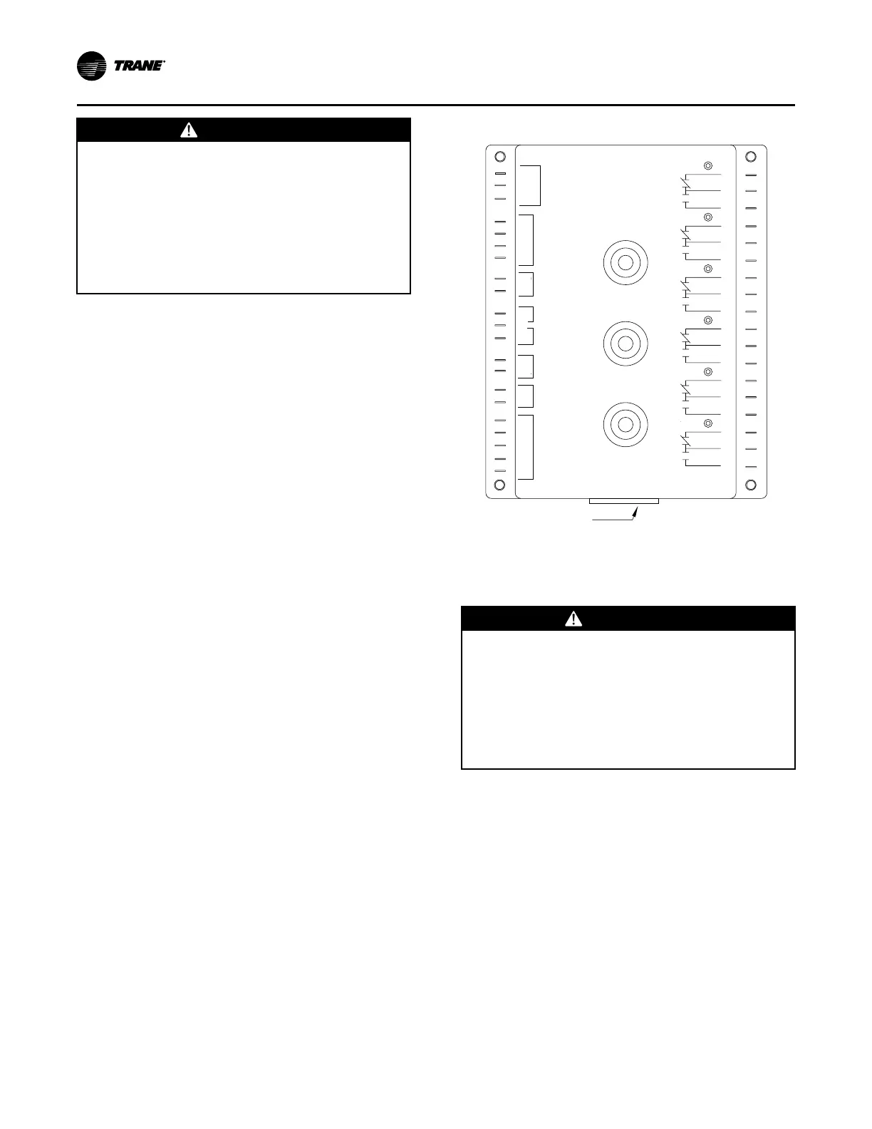
Figure 71. W7100G chilled water controller
SETPOINT °F
RESET °F
CONTROL
BAND °F
Test Plug Socket
(Remove red dust cover)
ECONO
24 VAC
CHANGE
OVER
# STAGES
SENSOR
RESET
REMOTE
SETPOINT
SATELLITE
COOL
COOL
COOL
COOL
COOL
COOL
B
C
A
B
C
A
B
C
A
B
C
A
B
C
A
B
C
A
6
5
4
3
2
1
GND
TR
TR
W
R
B
Y
10
9
T
T1
8
7
6
P
P1
5
4
3
2
1
Chilled Water Sensor Checkout
(Honeywell Sensor)
WWAARRNNIINNGG
HHaazzaarrddoouuss VVoollttaaggee!!
FFaaiilluurree ttoo ddiissccoonnnneecctt ppoowweerr bbeeffoorree sseerrvviicciinngg ccoouulldd
rreessuulltt iinn ddeeaatthh oorr sseerriioouuss iinnjjuurryy..
DDiissccoonnnneecctt aallll eelleeccttrriicc ppoowweerr,, iinncclluuddiinngg rreemmoottee
ddiissccoonnnneeccttss bbeeffoorree sseerrvviicciinngg.. FFoollllooww pprrooppeerr
lloocckkoouutt//ttaaggoouutt pprroocceedduurreess ttoo eennssuurree tthhee ppoowweerr
ccaann nnoott bbee iinnaaddvveerrtteennttllyy eenneerrggiizzeedd.. VVeerriiffyy tthhaatt nnoo
ppoowweerr iiss pprreesseenntt wwiitthh aa vvoollttmmeetteerr..
1. Verify that the main power disconnect switch and
the control circuit switch 1S2, in the unit control
panel, is “OFF”.
2. At the temperature controller, disconnect the wire
connected to terminal T1. Use a digital ohmmeter
to measure the resistance across terminal T and the
wire removed from terminal T1.
3. Use the conversion chart in Figure 37 to convert the
measured resistance to an equivalent temperature.
4. Measure the actual temperature at the sensor
location. If the measured resistance in step 2 is not
within ± 10.0 ohms of the actual temperature, the
sensor is out of range; replace it.
PPrree--SSttaarrtt