40
SS-SVX11K-EN
Installation Mechanical
Location Requirements
Isolation
To minimize unit sound and vibration transmission,
one of the following installation methods should be
used:
• Install the unit directly on an isolated (detached)
concrete pad or on isolated concrete footings
located at each unit load point. OR
• Install the optional neoprene or spring isolators at
each mounting location. See Unit Isolation section.
Foundation
Ground Level Installation
• If the unit is installed at ground level, elevate it
above the snow line.
• Provide concrete footings at each support location
or a slab foundation for support.
• See Weights table in Dimensions and Weights
chapter for the unit operating weights.
• See Unit Mounting section for mounting locations
and point loading weights when constructing the
footing foundation.
• Anchor the unit to the footings or slab using hold
down bolts or isolators.
• Isolators should be installed to minimize the
transmission of vibrations into the building. See
Unit Isolation section.
Rooftop Applications
For rooftop applications, ensure the roof is strong
enough to support the unit. See Weights table in
Dimensions and Weights chapter for the unit operating
weights.
Anchor the unit to the roof with hold-down bolts or
isolators. Follow the instructions in Unit Isolation
section for proper isolator placement and installation.
Check with a roofing contractor for proper
waterproofing procedures.
Leveling the Unit
Before tightening the mounting bolts, level the unit
carefully. Use the unit base rail as a reference. Level the
unit to within 1/4 inch over its entire length. Use shims
if non-adjustable isolators (neoprene) are used.
If adjustable isolators (spring) are used, ensure that the
proper isolator housing clearance is maintained while
leveling the unit. Isolators are identified by color and/or
an isolator part number. Shims under the isolators may
be required if the unit cannot be leveled using the
isolator leveling bolt.
Rigging and Lifting
WWAARRNNIINNGG
HHeeaavvyy OObbjjeecctt!!
FFaaiilluurree ttoo ffoollllooww iinnssttrruuccttiioonnss bbeellooww ccoouulldd rreessuulltt iinn
uunniitt ddrrooppppiinngg wwhhiicchh ccoouulldd rreessuulltt iinn ddeeaatthh oorr
sseerriioouuss iinnjjuurryy,, aanndd eeqquuiippmmeenntt oorr pprrooppeerrttyy--oonnllyy
ddaammaaggee..
EEnnssuurree tthhaatt aallll tthhee lliiffttiinngg eeqquuiippmmeenntt uusseedd iiss
pprrooppeerrllyy rraatteedd ffoorr tthhee wweeiigghhtt ooff tthhee uunniitt bbeeiinngg
lliifftteedd.. EEaacchh ooff tthhee ccaabblleess ((cchhaaiinnss oorr sslliinnggss)),, hhooookkss,,
aanndd sshhaacckklleess uusseedd ttoo lliifftt tthhee uunniitt mmuusstt bbee ccaappaabbllee
ooff ssuuppppoorrttiinngg tthhee eennttiirree wweeiigghhtt ooff tthhee uunniitt.. LLiiffttiinngg
ccaabblleess ((cchhaaiinnss oorr sslliinnggss)) mmaayy nnoott bbee ooff tthhee ssaammee
lleennggtthh.. AAddjjuusstt aass nneecceessssaarryy ffoorr eevveenn uunniitt lliifftt..
WWAARRNNIINNGG
IImmpprrooppeerr UUnniitt LLiifftt!!
FFaaiilluurree ttoo pprrooppeerrllyy lliifftt uunniitt iinn aa LLEEVVEELL ppoossiittiioonn
ccoouulldd rreessuulltt iinn uunniitt ddrrooppppiinngg aanndd ppoossssiibbllyy
ccrruusshhiinngg ooppeerraattoorr//tteecchhnniicciiaann wwhhiicchh ccoouulldd rreessuulltt iinn
ddeeaatthh oorr sseerriioouuss iinnjjuurryy,, aanndd eeqquuiippmmeenntt oorr
pprrooppeerrttyy--oonnllyy ddaammaaggee..
TTeesstt lliifftt uunniitt aapppprrooxxiimmaatteellyy 2244 iinncchheess ((6611 ccmm)) ttoo
vveerriiffyy pprrooppeerr cceenntteerr ooff ggrraavviittyy lliifftt ppooiinntt.. TToo aavvooiidd
ddrrooppppiinngg ooff uunniitt,, rreeppoossiittiioonn lliiffttiinngg ppooiinntt iiff uunniitt iiss
nnoott lleevveell..
See Weights table in Dimensions and Weights chapter
for unit weights. See Table 6, p. 42 for center-of-gravity
information.
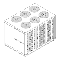
1. Rig condensing unit as shown in Figure 28, p. 41
and Figure 29, p. 41. Attach adequate strength
lifting slings to all four lifting brackets. Do not use
cables, chains, or slings except as shown.
2. Install spreader bars as shown in Figure 28, p. 41 to
protect the unit and to facilitate a uniform lift.
Minimum distance between lifting hook and top of
unit is 7 feet.
3. Test-lift the unit to ensure it is properly rigged and
balanced. Make any necessary rigging adjustments.
4. Lift the unit and position into place.