RRU-SVX02F-EN 35
Indirect Gas-Fired Heating Start-Up
Important: The following procedure must be followed
for the unit heating section to function
properly. The following procedures are to
be performed after all electrical and gas
connections to the unit have been
completed and the outdoor air damper and
evaporator fan operation have been verified
and are operating satisfactorily.
Refer to “Sequence of Operation,” p. 18 for additional
information.
Tools Required
• Voltage meter (µA)
•Amp meter
• Gas pressure gauge (2)
• Temperature probe
• Service mirror
• Small refrigeration screwdriver
• 5/16-in. Nut driver
• 1/2-in. Open end wrench
Important: Remove the outdoor air inlet aluminum
mesh filters if they are not clean prior to
proceeding with burner start-up.
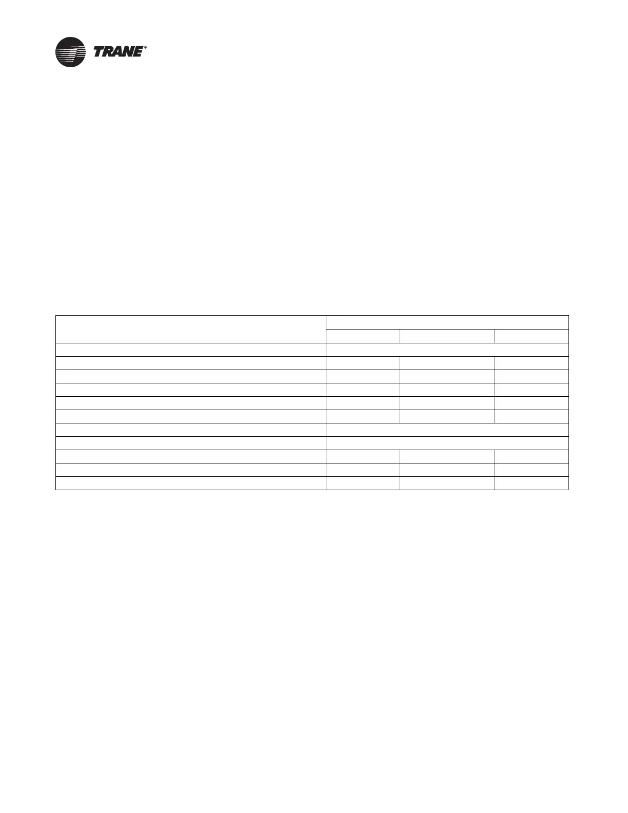
Table 5. Gas heater operating data
Heating Input Rate - BTUH
250,000 350,000 400,000
Fuel Natural Gas ONLY
Minimum Supply Gas Pressure (in. wc) 7 7 7
Maximum Supply Gas Pressure (in. wc) 14 14 14
Maximum (High-Fire) Manifold Gas Pressure (in. wc) 3.9 4.8 5.0
Minimum (Low-Fire) Manifold Gas Pressure (in. wc) 0.041 0.058 0.058
Combustion Blower SuctionPressure (Min. to Max. With Gas Valve Closed) -4.3 to -2.5 in. wc -4.3 to -1.7 in. wc -4.3 to -1.5 in. wc
Minimum Flame Sensing Current 1.5 Microamps DC
Normal Sensing Current Range 3.0 to 6.0 Microamps DC
RRUCM Voltage Output Range to MGA (Vdc) 2.0 to 4.0 2.0 to 5.2 2.0 to 8.0
Flue Gas Temperature Rise Above Ambient (°F) 180 to 200 280 to 300 350 to 370
Flue Gas Content—% CO
2
Natural Low/High 6.0/9.5 6.0/9.5 6.0/10.5
Note: Adjust the combination gas valve regulator gas valve to vary the manifold gas pressure and burner input within the range shown. Do not exceed
pressure as listed in this table, under any circumstances. Use combination readings (CO and O
2
and a flow meter to determine exact inputs.
 Loading...


