Indirect Gas-Fired Heating Start-Up
36 RRU-SVX02F-EN
STEP 1: Confirm Inlet Gas Pressure and Gas
Flow
Close the burner gas train manual shut-off valve located
upstream of the Combination Gas Valve. Connect gas
pressure gauge upstream of the burner gas train manual
shut-off valve. Do NOT expose gas controls to pressures
above 1/2 psi (14 in. wc). Minimum inlet gas pressure
required for full modulation is 1/4 psi (7 in. wc). Refer to
unit data plate for operating gas pressure range. Confirm
gas flow and bleed gas line if needed before proceeding to
the next step.
STEP 2: Burner Starting Sequence and Burner
Ignition
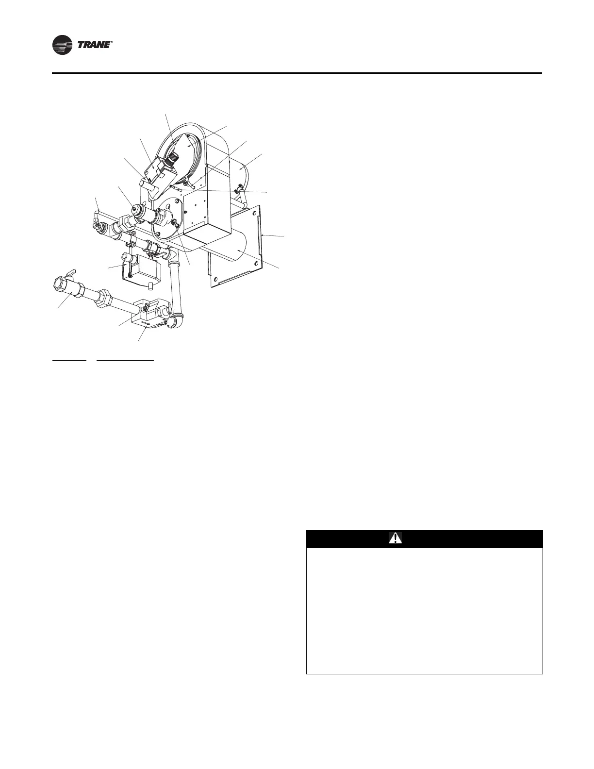
Figure 15 illustrates the gas train main components.
Open burner gas train manual shut-off valve. Open
Combination Gas Valve manual shut-off. At unit ROD
override HEAT binary output ON. Refer to ““Occupied”
Heating Mode,” p. 19 for Burner Starting and Sequence of
Operation. If the burner fails to light or goes out after
lighting, the burner will go into safety lock-out. A single
ignition retry will occur. Power must be turned off to the
RRUCM to initiate another ignition sequence. Use burner
view port to observe burner flame. Proper flame should be
solid blue.
STEP 3: Firing Rate Test
The burner includes a fixed bypass for low-fire operation.
Correct gas pressure assures proper low-fire. Low-fire gas
flow adjustments should not be attempted. The high-fire
firing rate was factory set. If required, adjustments should
only be made by a trained technician. It is recommended
the manufacturer’s technical support team be contacted
prior to making gas flow adjustments.
Override analogue Heat Modulation Signal to check
burner flue gas content. Refer to Table 5, p. 35 for flue gas
content. Override Heat Modulation Signal to 0 to check
low-fire operation and to 100 to check high-fire operation.
The Main Gas Valve regulator would be used to make
high-fire gas flow adjustments. Gas pressure to the burner
is read by connecting gas pressure gauge to the Burner
Gas Pressure Tap.
The Combustion Air Damper set screws are preset at the
locations that correspond with burner low fire and burner
rated high fire capacity. At the low fire setpoint there will
be a slight opening between the damper and the air inlet.
Drill index #40 (0.098 in.) can be used as a reference for the
opening size. Ensure that the damper is flush to the inlet
ring by using a service mirror to check the seal between
the damper and the inlet ring. Minor adjustment can be
done by adjusting the three machine screws on the inlet
ring. Major adjustment can be done by loosening the bolt
(do NOT remove the bolt) only enough for the rod to be
adjusted. In the event that the pressure switch fails to
operate, check the aluminum pick-up tubes to be certain
that the tubes are not obstructed and confirm that the tube
connections to the burner Fan Failure pressure Switch are
tight and secure.
Figure 15. Burner assembly and gas train
PART ID
A
B
C
D
E
F
G
H
I
J
K
L
M
N
O
P
DESCRIPTION
Burner Blower Motor
Combustion Air Inlet
Combustion Air Pressure Tube
Combustion Air Damper
Combustion Damper Actuator
Combustion Damper Hi-Fire Stop
Sight Glass (2)
Burner Gas Pressure Tap
Combination Gas Valve
Gas Regulator (To Burner)
Modulating Gas Valve Actuator
Low Fire Gas Bypass Tube
Electronic Ignition Controller
Burner Mounting Plate
Burner Outlet (Behind Plate Not Shown)
Inlet Manual Shut-Off with Pressure Tap
1
2
$
&
)
'
%
(
+
0
/
*
,
-
3
.
XEH
HU
XDWRU
H6WRS
S
H
HU
XDWRU
EH
ROOHU
H
RW6KRZQ
VVXUH7DS
WARNING
Fire and Carbon Monoxide Hazards!
Failure to follow these instructions could result in death
or serious injury or equipment or property-only
damage.
Do NOT exceed gas supply input beyond rated capacity
as shown on unit data plate as it will result in improper
burner operation. Improper burner operation will cause
the burner to soot and create unsafe operating
conditions, including excessive soot in the flue which
could ignite. Over-firing the burner could also cause
damage to the heat exchanger, which could result in
combustion gases leaking into the occupied space.
 Loading...


