86
RTAA-IOM-3
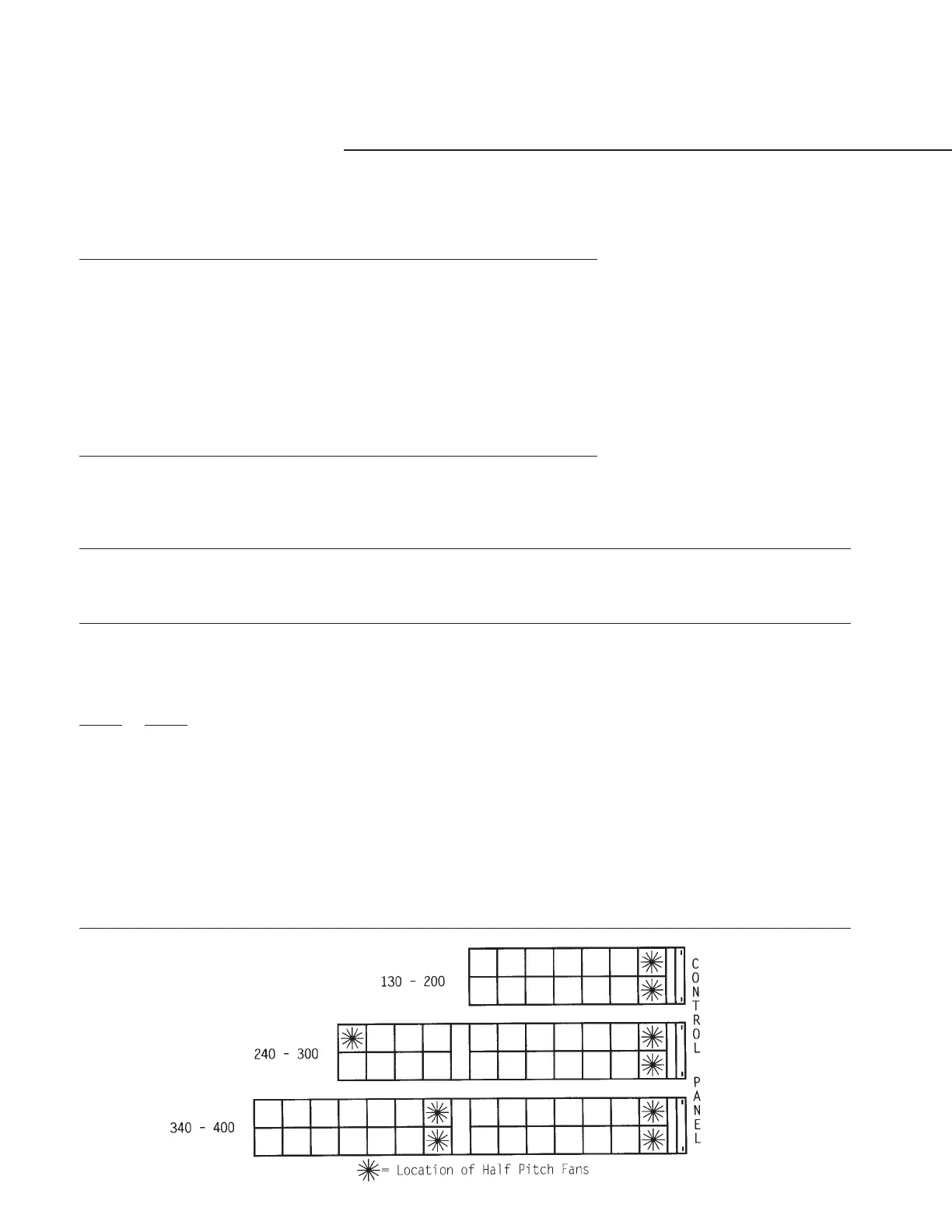
Figure 46
Fan Configurations - RTAA 130-400 Tons - 0 F Minimum Ambient
The 0 F AMBIENT OPTION will have Half Airflow (Half Pitch Blade) Fan.
# Of Fans # Of Fans UCM Outputs
Tons Circuit #1 Circuit #2 Per Circuit Fan Steps/Circuit
130 5* 6* 4 9 & 10 respectively
140 5* 6* 4 9 & 10 respectively
155 6* 6* 4 10 & 10 respectively
170 7* 6* 4 11 & 10 respectively
185 7* 7* 4 11 & 11 respectively
200 7* 7* 4 11 & 11 respectively
215 7* 7* 4 11 & 11 respectively
240 10** 7* 4 9 & 11 respectively
270 12** 7* 4 10 & 11 respectively
300 14** 7* 4 11 & 11 respectively
340 10** 14** 4 9 & 11 respectively
370 12** 14** 4 10 & 11 respectively
400 14** 14** 4 11 & 11 respectively
*The first fan on each single compressor circuit is a Half Airflow (Half Pitch Blade) Fan.
**The first two fans on each dual compressor circuit are Half Airflow (Half Pitch Blade) Fans.
For 0 F AMBIENT OPTION air-cooled (RTAA) Chillers, the mapping of UCM outputs to fan staging shall be as follows:
Fan Contactor 5 & 10 Fan Circuit 6 & 12 Fan Circuit 7 & 14 Fan Circuit
Circuit #1 K9 K10 K11 K12 K9 K10 K11 K12 K9 K10 K11 K12
Circuit #2 K13 K14 K15 K16 K13 K14 K15 K16 K13 K14 K15 K16
Number of
Fans/Contactor
Single Comp. Ckt. 1* 1 1 2 1* 1 2 2 1* 1 2 3
Dual Comp. Ckt. 2* 2 2 4 2* 2 4 4 2* 2* 2 4 6
* = Half AirFlow Fan
Fan Steps
Single Dual
Compr Compr
Ckt Ckt
0.0 0.0 –––– –– –– ––––
0.5 1 x––– x– –– x–––
1 2 –x–– –x –– –x––
1.5 3 xx–– xx –– xx––
2 4 –xx– –– x– ––x–
2.5 5 xx x– x– x– x–x–
3 6 –x–x –x x– –––x
3.5 7 x x – x x x x – x – – x
4 8 –xxx –– xx –x–x
4.5 9 xxxx x– xx xx–x
5.5 11 –––– xx xx x–xx
6.5 13 –––– –– –– xxxx
X = ON