Module Power and Miscellaneous I/O
RTHC-SVD01B-EN 73
13-4 b. I/O Terminals
For the checkout of the I/O, refer to the Chiller Wiring Diagrams for
both high and low voltage circuits. All voltages are measured between
terminal pairs specified unless otherwise indicated. Nominal voltages
are given and may vary by +
5%. Unregulated voltages (unreg) or 115
VAC voltages may vary by +
15%.
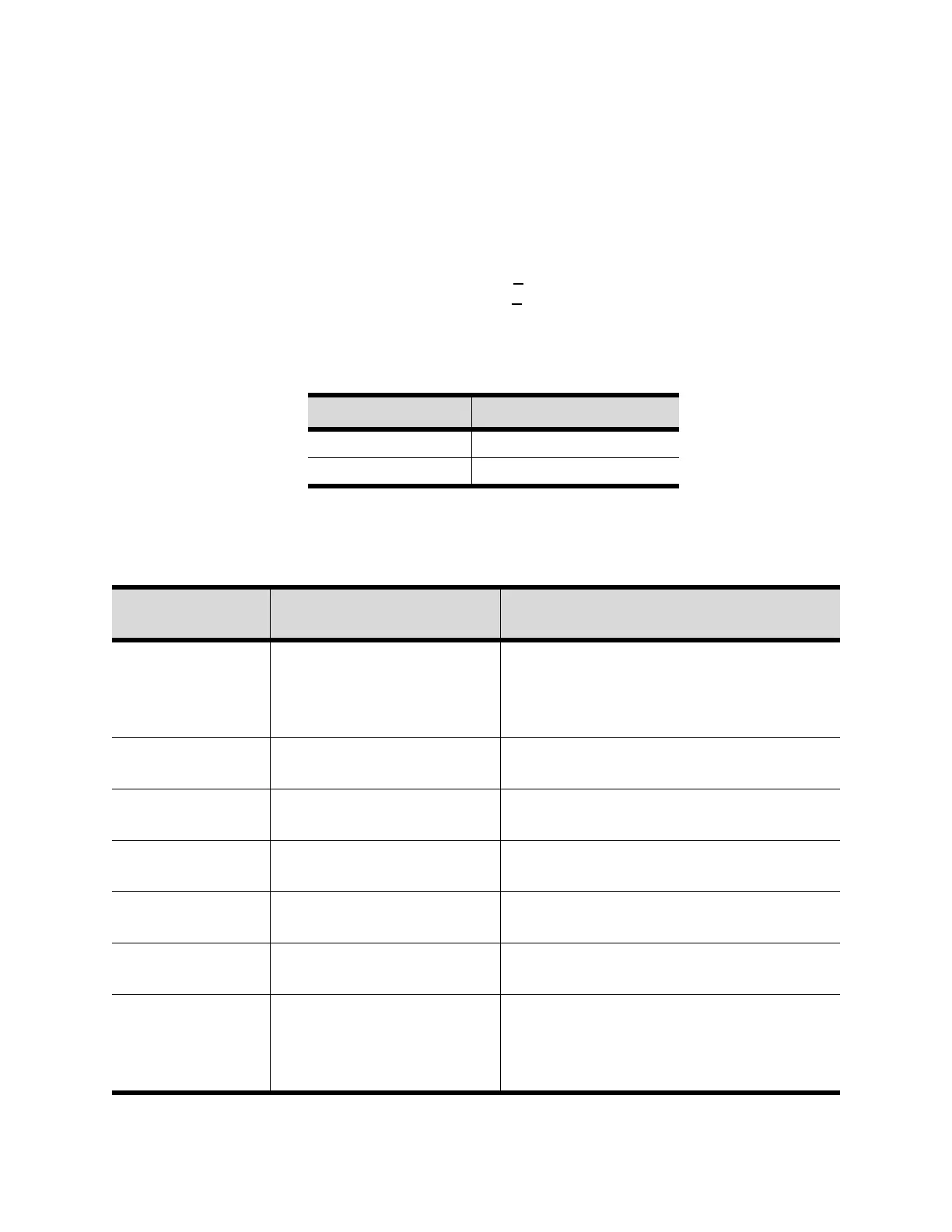
Table 13-2: Test Point Voltages for 1U1 Module
Test Point Voltage (VDC)
TP1
4.8 to 5.2
TP2 23 to 25
Table 13-3: Chiller Module Nominal Terminal Input and Output (1U1)
Terminal
Designation
Description of Circuit
Normal Terminal Voltages for Various
Conditions
J1A-1, 3 (BK)
J1A-2, 4 (W)
J1B-3 (BK)
J1B-4 (W)
IPC Communications 19.2 kbaud serial data, RS485 signal level.
Refer to Interprocessor Communication (IPC)
J2-1 or 3 to
J2-2 or 4
Input Power
24 VAC, Refer to Power Supply
J3-1, 2 Evap. Entering Water Temp.
Sensor
Refer to Temperature Sensor Checkout
J3-3, 4 Evap.Leaving Water Temp.
Sensor
Refer to Temperature Sensor Checkout
J3-5, 6 Condenser Entering Water
Temp. Sensor
Refer to Temperature Sensor Checkout
J3-7, 8 Condenser Leaving Water
Temp. Sensor
Refer to Temperature Sensor Checkout
J4-2,1 Oil Return Gas Pump Fill Sol
Valve and Coil:
Solenoid cycles on and off on a 1minute+50
sec. cycle for a variable duty cycle while the
chiller is running. This valve opens a vent line to
the evaporator to allow filling of the chamber.