Module Power and Miscellaneous I/O
72 RTHC-SVD01B-EN
13-3 h. LEDs
There are four LEDs located to the right of J1 of the CLD module. The
left most TST LED should be on continuously.
If the TST LED blinks, it indicates the processor is repeatedly
being reset. The module needs to be replaced if this is occurring.
The second LED from the left is the +5 VDC LED and should also be
on continuously. It will go out if power drops below normal operating
voltage. The TX LED (third from the left) should blink every second or
two, as the CLD transmits on the IPC. The RX LED (fourth from the
left) should blink continuously, indicating that other modules are com-
municating.
13-4. Chiller Module (1U1)
13-4 a. Test Points
There are two test points (TP) associated with the Chiller module.
They are easily read with a DC voltmeter by probing the PC board sol-
der pads found in the upper left hand corner of the module. The posi-
tive meter lead should be connected to the pad while referencing the
negative meter lead to the board edge ground plane.
Do not use the aluminum module enclosure as the reference it
has an anodized surface with insulating properties.
The DC voltages shall be within the following tolerances. If not, replace
the module.
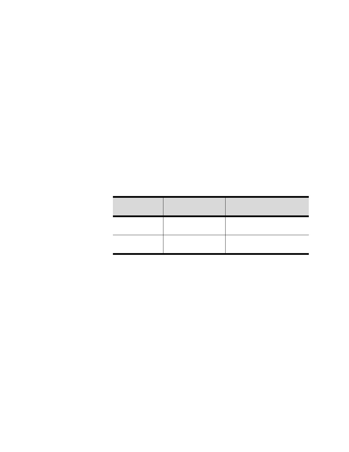
Table 13-1: CLD Nominal Terminal Voltage (1U4)
Terminal
Designation
Description of
Circuit
Nominal Terminal Voltages
for Various Conditions
J1-1 (BK)
J1-2 (W)
IPC Communication
19.2K Baud serial data 5 V signal
level
J2-1, 2 24 VAC Power 18-30 VAC, neither side
grounded