Module Power and Miscellaneous I/O
RTHC-SVD01B-EN 79
13-6. Stepper Module (1U3)
13-6 a. Test Points
There are four test points (TP) associated with the Stepper module.
They are easily read with a DC voltmeter by probing the PC board sol-
der pads found in the upper left hand corner of the module. The posi-
tive meter lead should be connected to the pad while referencing the
negative meter lead to the board edge ground plane.
Do not use the aluminum module enclosure as the reference. The
enclosure has an anodized surface with insulating properties.
The DC voltages shall be within the tolerances specified below. If not
replace the module.
13-6 b. I/O Terminals
For the checkout of the I/O, refer to the Chiller Wiring Diagrams for
both high and low voltage circuits. All voltages are measured between
terminal pairs specified unless otherwise indicated. Nominal voltages
are given and may vary by +
5%. Unregulated voltages (unreg) or 115
VAC voltages may vary by +
15%.
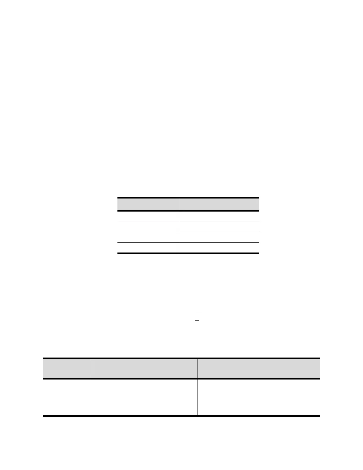
Table 13-6: Test Point Voltages for 1U3 Module
Test Point Voltage (VDC)
TP1 26 to 48
TP2 4.8 to 5.2
TP3 11 to 16
TP4 23 to 25
Table 13-7: Stepper Module Nominal Terminal Voltages (1U3)
Terminal
Designation
Description of Circuit
Normal Terminal Voltages for Various
Conditions
J1-1, 3 (BK)
J1-2, 4 (W)
IPC Communications 19.2 kbaud serial data, RS485 signal level.
Refer to Interprocessor Communication
(IPC)
NOTE: Polarity sensitive