Module Power and Miscellaneous I/O
RTHC-SVD01B-EN 87
4. Check for a diagnostic at the display indicating loss of IPC com-
munications with the TCI module. This could indicate IPC bus
problems or a dead TCI module. The TCI module needs to
receive 4 good packets of data from the Chiller before it will talk
on the ICS link.
13-8 c. I/O Terminals
For the checkout of the I/O, refer to the Chiller Wiring Diagrams for
both high and low voltage circuits. All voltages are measured between
terminal pairs specified unless otherwise indicated. Nominal voltages
are given and may vary by +
5%. Unregulated voltages (unreg) or 115
VAC voltages may vary by +
15%.
13-9. Printer Interface (1U7)
13-9 a. Test Points
There are two test points (TP) associated with the Printer Interface
module. They are easily read with a DC voltmeter by probing the PC
board solder pads found in the upper left hand corner of the module.
The positive meter lead should be connected to the pad while refer-
encing the negative meter lead to the board edge ground plane. The
DC voltages shall be within the previous tolerances. If not, replace the
module.
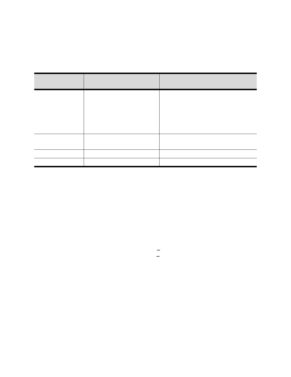
Table 13-13: TCI-COMM 3 or 4 Module Nominal Terminal Voltages (1U6)
Terminal
Designation
Description of Circuit
Normal Terminal Voltages for Various
Conditions
J1A-3 (BK)
J1A-4 (W)
*J1A-1(BK)
*J1A-2 (W)
* If additional
modules are used.
IPC Communications 19.2 kbaud serial data, RS485 signal level.
Refer to Interprocessor Communication
(IPC)
J2-1 or 3 to
J2-2 or 4
Input Power 115 VAC, Refer to Power Supply
J3-1, 2 Twisted Pair to Tracer Comm 3 or Comm 4 signal
J3-3, 4 Twisted Pair to tracer Comm 3 or Comm 4 signal