Module Power and Miscellaneous I/O
88 RTHC-SVD01B-EN
Do not use the aluminum module enclosure as the reference as it
has an anodized surface with insulating properties.
13-9 b. Recommended Printer Setup
A serial printer must be used with the printer interface module. Several
settings in the UCP2 must match the printer settings identically.
The suggested serial communications settings in the UCP2 are in bold
print below.
Located in Service Settings menu:
Printer Option: (Installed, Not Installed)
Set it to Installed.
NOTE: This setting is under the password protected Machine Configu-
ration Group (+-+-+-) which must be “Installed” before the remaining
displays will appear under the non-password protected items in Ser-
vice Settings.
[ ] Print on Time Interval: (Enable, Disable)
[ ] Print Time Interval: (1-24 hrs)
[ ] Print on Diagnostic: (Enable, Disable)
[ ] Number of Pre-Diagnostic Reports: (1-5)
[ ] Printer, Baud Rate: 9600
[ ] Printer, Parity: None
[ ] Printer, Data Bits: 8
[ ] Printer, Stop Bits: 1
[ ] Printer Handshaking: XON-XOFF
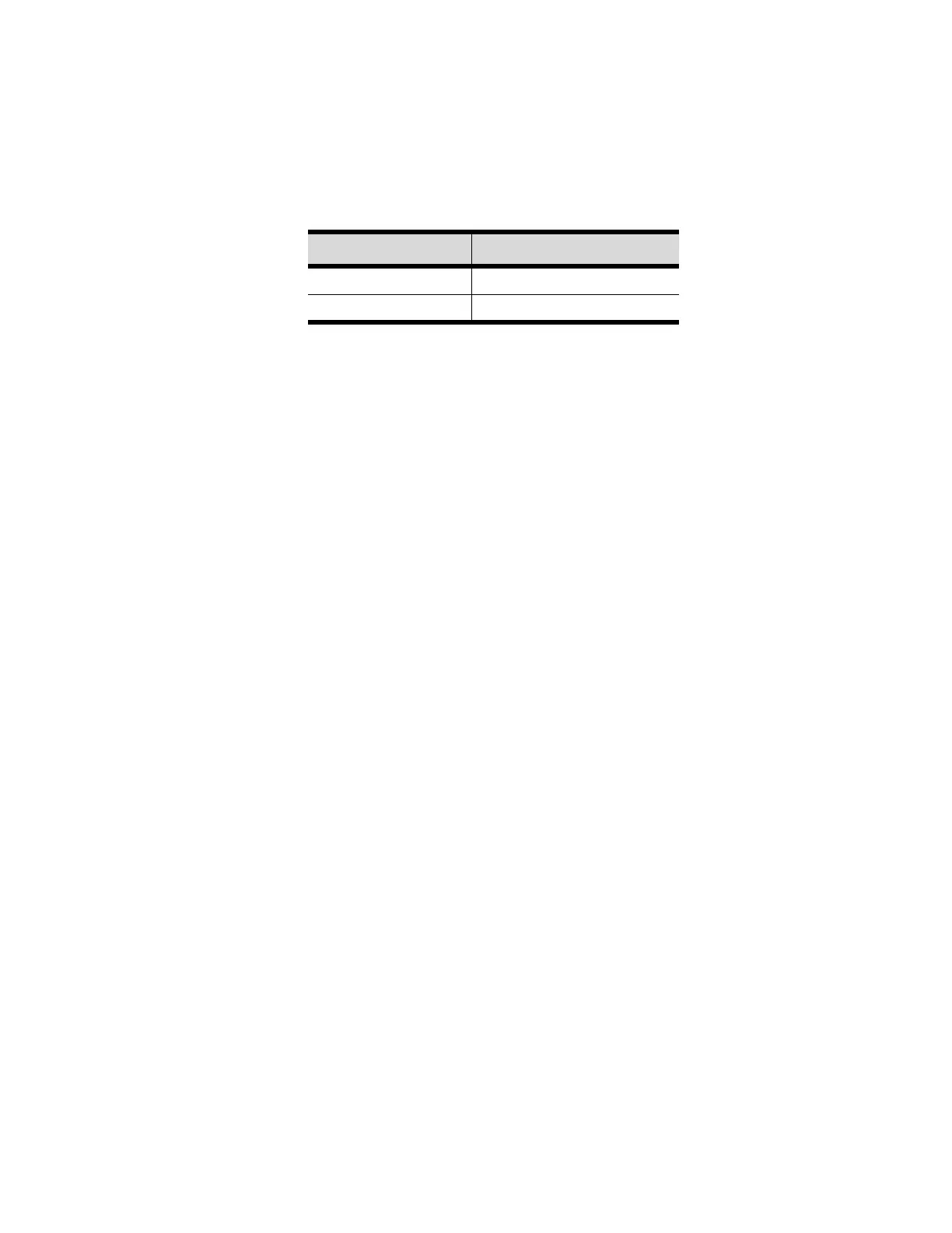
Table 13-14: Test Point Voltages for 1U7 Module
Test Point Voltage (VDC)
TP1 4.8 to 5.2
TP2 23 to 25