EasyManua.ls Logo

Trane TMM5B0A24M21SAA User Manual

Trane TMM5B0A24M21SAA
13 pages
To Next Page IconTo Next Page
Page #1 background imageLoading...
Page #1 background image
WALL-MOUNT AIR HANDLERS
2-3TON COOLING/HEAT PUMP
TMM5B0A24M21SAA
TMM5B0B30M21SAA
TMM5B0B36M31SAA
ALL phases of this installation must comply with NATIONAL, STATE AND LOCAL CODES
Important: This Document is customer property and is to remain with this unit.
Installer’s Guide
Section 1. Features
1.1 Standard Features
1.2 Optional Accessories
5, 7.5 and 10 kW SINGLE PHASE ELECTRIC
HEATERS
- Circuit breakers are standard on all single
phase 5,
7.5 and 10 kW heaters.
The TMM5B series wall mount air handler is designed for installation in a closet, utility room, alcove
and can be wall mounted. These versatile units are applicable to air conditioning and heat pump
applications. Field installed electric resistance heaters are available.
All aluminum coil.
Blower and coil slide out easily for maintenance.
Factory-sealed cabinet certified to achieve 2% or
less air leakage rate at 1.0 inch water column.
Front or bottom return air.
Painted finish on galvanized steel.
Sturdy polycarbonate drain pans.
- Air handler has factory installed drain pans and
is shipped for upflow applications only.
208/230 VAC operation.
Multi-speed direct drive blower constant torque
ECM motor with fan-off time delay programming.
Factory installed R-410A thermal expansion
valve.
Stud or wall mounting installation.
Fully insulated cabinet.
3/4'' NPT primary and secondary drains.
AHRI certifird and ETL listed.
18-GF13D1-1A-EN
Question and Answer IconNeed help?

Do you have a question about the Trane TMM5B0A24M21SAA and is the answer not in the manual?
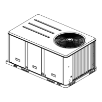
Trane TMM5B0A24M21SAA Specifications

General IconGeneral
Product TypeAir Conditioner
Nominal Cooling Capacity (tons)2
Voltage208/230
Cooling Capacity24000 BTU/H
Refrigerant TypeR-410A
Phase1
Sound Level (Outdoor Unit)72 dB

Summary

Section 1. Features

Section 2. Safety Information

Safety Warnings and Precautions

Covers critical safety precautions, electrical hazards, chemical warnings, and general safety for installation and operation.

Section 3. Installation Instructions

3.3 Duct Work Installation

Requirements and best practices for designing and installing ductwork systems for optimal airflow.

3.4 Condensate Drain System

Instructions for correctly installing and trapping condensate drain lines to prevent leaks and damage.

3.8 Wiring and Grounding

Covers power, control wiring, grounding procedures, and motor speed tap selection.

3.11 Sequence of Operation

Describes how the unit operates in cooling, heat pump, and electric heat modes based on thermostat signals.

3.12 Operational Checkout

A checklist to ensure the system is installed correctly and functioning properly in all modes.

Section 4. Wiring Diagrams

Section 6. Performance and Electrical Data

Related product manuals