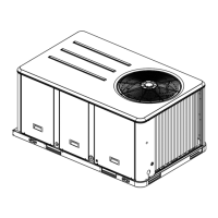
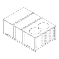
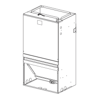
7.1 UNIT DIMENSIONS
Fig. 5-1 DIMENSIONS
Low voltage
connection
Breaker switch
(for electric heater
only)
D1
D
W1
W
H
Return air opening
High voltage connection
7/8" dia knock outs
Vapor line connection
copper (sweat)(3/4"dia pipe)
Liquid line connection
copper (sweat)(3/8"dia pipe)
All units are configured for vertical upflow.
Units cannot be installed in any other configuration.
Auxiliary drain connection 3/4"
female pipe thread (NPT)
Primary drain conncetion 3/4"
female pipe thread (NPT)
Front return shown. Units may
also be installed as bottom
return. See the applications
section for more detail.
NOTE:Hand tighten only
Section 7 Dimensional Data
DIMENSIONAL DATA
Model
Dimensions inch [mm]
H W
D
UNIT WEIGHT
/SHIPPING WEIGHT
(LBS.[kg])
TMM5B0A24M21SAA
W1 D1
TMM5B0B30M21SAA
TMM5B0B36M31SAA
39-1/2˝[1004]
97/115 [44]/[52]
22˝[559] 18-3/4˝[477] 19˝[483] 9-1/2˝[242]
39-1/2˝[1004]
97/115 [44]/[52]
22˝[559] 18-3/4˝[477] 19˝[483]
Flow
Control
TXV
36-1/2˝[928] 79/93 [36]/[42]20-1/2˝[522] 16-5/8˝[422] 15˝[381]
9-1/2˝[242]
TXV
TXV
9-1/2˝[242]
 Loading...