The air distribution system has the greatest effect on airflow. The duct system is totally controlled by the contractor. For this reason, the contractor
should use only industry-recognized procedures.
Heat pump systems require a specified airflow. Each ton of cooling requires between 350 and 450 cubic feet of air per minute (CFM), or 400 CFM
nominally.
Duct design and construction should be carefully done. System performance can be lowered dramatically through bad planning or workmanship.
Air supply diffusers must be selected and located carefully. They must be sized and positioned to deliver air along the perimerter of the space. If
they are too small for their intended airflow, they become noisy. If they are not located properly, they cause drafts. Air grilles must be properly sized
to carry air back to the blower.If they are too small, they also cause noise.
The installers should balance the air distribution system to ensure proper quiet airflow to all rooms in the home. This ensures a comfortable living
space.
Airflow performance data is based on cooling performance with a coil and no filter in place. Select performance table for appropriate unit size
external static applied to unit allows operation within the minimum and maximum limits shown in table below for both cooling and electric heat
operation.
Airflow Performance(Standard CFM)
1. Airflow based upon dry coil at 230V with no electric heat,no filter. For 24, 30,and 36 sizes, airflow at 208V is approximately the same as
230V because the mult-tap ECM motor is a constant torque motor. The torque doesn’t drop off at the speeds in which the motor operates.
2. Airflow is equivalent for front or bottom return configurations.
3. SCFM is nearly the same with cooling performance airflow, the gap is in the 1 to 2%.
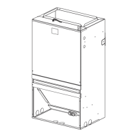
Section 6. Performance and Electrical Data (WALL-MOUNT AIR HANDLERS ARE SUITABLE
FOR MOBILE HOME APPLICATIONS)
--- Shaded boxes represent airflow outside the required 300-450 cfm/ton.
* When TMM5B0A24M21SAA
is used with 1.5ton outdoor unit ,select SCFM between 450 and 675.
NOTES:
0
0.1
0.18 0.2 0.3
0.4 0.5 0.6 0.7 0.8
Tap(5) 913 881 848 848 818 792 763 731 691 650
Tap(4)-Factory 825 787 756 753 717 682 650 617 580 540
Tap(3) 737 700 666 663 630 589 550 511 474 436
Tap(2) 675 632 598 596 555 521 480 440 399 366
Tap(1) 590 548 512 499 455 430 368 338 309 263
Tap(5) 1362 1325 1280 1266 1238 1197 1159 1119 1080 1040
Tap(4) 1282 1242 1195 1176 1151 1111 1071 1028 975 936
Tap(3) 1267 1225 1178 1143 1120 1078 1036 993 942 897
Tap(2)-Factory 1157 1111 1061 1052 1016 971 929 884 842 802
Tap(1) 1077 1028 978 965 932 886 850 804 768 732
Tap(5) 1362 1325 1280 1266 1238 1197 1159 1119 1080 1040
Tap(4)-Factory 1282 1242 1195 1176 1151 1111 1071 1028 975 936
Tap(3) 1267 1225 1178 1143 1120 1078 1036 993 942 897
Tap(2) 1157 1111 1061 1052 1016 971 929 884 842 802
Tap(1) 1077 1028 978 965 932 886 850 804 768 732
36
30
24
Model
BLOW ER
SPEEDS
EXTERNAL STATIC PRESSURE(in.w.c.)
TMM5B
 Loading...