Installation
12 SS-SVX006C-EN
The clearance around the unit to the nearest wall or
obstruction should be at least 1 time’s (1×) the unit’s width
to ensure adequate airflow to the coil(s) (see Figure 5 and
Figure 6). Space multiple units at least 2 times (2×) the
unit’s wi
dth when placing them side by side. Ensure hot
exhaust air is not directed toward the air inlet of an
adjacent unit. When placing units end to end, allow at least
4 feet of space between units. Avoid areas where heavy
snow will accumulate at air inlet and outlet openings.
If the unit(s) are surrounded by three walls or if they are in
a pit, spa
ce them at least 2 times (2×) the unit’s width from
the nearest walls (see Figure 7, p. 12). The top of the unit
must be equa
l to the height of the walls or the pit. A stack
may be used, if necessary, to extend the air discharge. The
height of the extension must not exceed 10 feet.
Figure 6. Side clearance
Figure 7. Walled areas or pits
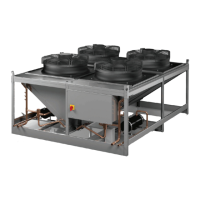
Receiver
Receivers are provided as an option for systems utilizing
flooded head pressure control. Receivers for TR-SCS
condensers are provided on a separate mounting base
frame. Position optional TR-SCS receiver(s) as close as
possible to the condenser inlet/outlet pipe stubs. Secure
the receiver base frame to the foundation using the
mounting holes in the base. (Receivers for TR-SCS-MC
condensers are factory mounted to the condenser frame.)
Figure 8. Receiver assembly
Head Pressure Control Valve
For TR-SCS condensers, the head pressure control valve
(HPCV) is shipped loose for field installation. The head
pressure control valve is to be located at the condenser
and brazed in line with the piping between the condenser
and receiver. For TR-SCS-MC condensers, the HPCV is
factory piped to the receiver.
Refrigerant Piping
Split air-cooled systems require a field installed copper
discharge line and copper liquid line between the
condenser and the evaporator. Dual circuited condensers
will require two sets of piping. Refer to the refrigeration
diagram provided with your unit for piping details.
Provide a permanent stand or support brace for the inlet/
o
utlet pipes within one foot of the condenser header to
prevent undue stress on soldered connections (see
Figure 5, p. 11). The refrigerant piping should be isolated
by vibra
tion isolating supports. Provide supports (clamps
or hangers) as necessary every 5 to 10 feet along piping
runs to minimize vibration and noise transmission. When
sealing openings in walls use a soft flexible material to
pack around the piping to reduce vibration transmission
and prevent pipe damage.
All refrigerant piping should be installed with high
tem
perature soldered joints. Use standard refrigeration
practices for piping supports, leak testing, dehydration
and charging of the refrigeration circuits.
Note: Re
fer to the Copeland Applications Data Guide for
more detailed
information regarding installation of
refrigerant piping.
The condenser is shipped with a dry nitrogen holding
charge wh
ich must be removed before piping and
charging the system. All refrigeration piping should be
installed with high temperature brazed joints. Use
standard refrigeration practices for piping, leak testing,
dehydration and charging of the refrigeration circuits. For
copper to copper brazing (piping liquid line or discharge
line), phosphorous alloy containing a minimum of 15%
1x WIDTH
2x
WIDTH
1x
WIDTH
TOP VIEW
2x
WIDTH
2x
WIDTH
10 FT. MAX.
STACK
AIR
FLOW
20 INCH MINIMUM
Outlet
Outlet
Inlet
Inlet
Junction Box
Pressure Relief
Valve
Sight Glass
(Optional)
Rotalock Valve (4X) with 7/8 in.
ODS Connection
Base Frame
Heater Pad
 Loading...