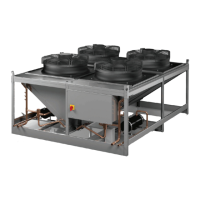
Table 4. Pressure drops
Refrigerant Type
Pressure Drop in
PSI/ft (Risers)
R407C 0.47
R410A 0.43
Installation
SS-SVX006C-EN 15
Note: When a receiver is used with the equipment, it
should be below the level of the condenser. The
liquid line from the condenser to the receiver
should be liberally sized to allow the refrigerant to
freely flow from the condenser to the receiver. The
total refrigerant line pressure drop must not
exceed 14 psig across the condenser and the
interconnecting piping to the evaporator and
condenser sections.
Head Pressure Control Valve Installation
(TR-SCS condenser only)
Refer to the refrigeration diagram provided with your unit
and see Figure 3, p. 9 for details on piping the head
pressure control valve to the condenser and receiver.
Receiver Pipe Installation (TR-SCS
condenser only)
Receiver inlets and outlets are equipped with RotoLock
valves that must have brazed pipe connections. It is
important to remove the valve from the adapter on the
receiver before brazing the refrigerant piping to it. Wrap
wet rags around the valve body to prevent the internal
parts from being damaged by the heat.
After brazing the pipe to the valve, remove and replace the
T
eflon
O-ring in the RotoLock adapter with the new one
which is cable-tied to the valve. When re-attaching the
valve to the receiver, apply thread lock to the adapter
threads to prevent it from vibrating loose. Tighten the
valve to the receiver and check it for leaks when
performing the steps given in Preparing System for
Charging section.
Utility Connections
WARNING
Proper Field Wiring and Grounding
Required!
Failure to follow code could result in death or serious
injury.
All field wiring MUST be performed by qualified
pe
rsonnel.
Improperly installed and grounded field
wiring poses FIRE and ELECTROCUTION hazards. To
avoid these hazards, you MUST follow requirements for
field wiring installation and grounding as described in
NEC and your local/state/national electrical codes.
Main Power and Control Wiring
Systems equipped with a remote condenser require field
wiring (see Figure 10, p. 14). The installer must provide
main power wiring to the remote condenser control box.
The condenser is provided with main power and control
terminal positions for connection of the field wiring
(supplied by others). Additional conductors may be
necessary depending on options selected.
Verify that the main power supply coincides with
the
voltage, phase and frequency information specified on the
system nameplate (see Figure 12, p. 16). The supply
voltage me
asured at the unit must be within ±10% of the
voltage specified on the nameplate. The nameplate also
provides the full load amps (FLA), the current that the unit
will draw under full design load, the minimum circuit
ampacity (MCA) for wire sizing, and the maximum fuse or
HACR (Heating, Air Conditioning, Refrigeration) breaker
size (MAX FUSE/CKT BKR) for circuit protection. The unit’s
nameplate is located inside the electrical box.
Pilot holes or electrical knock-outs for the
conduit are in
the bo
ttom of the electric box. A label stating MAIN
POWER INPUT is nearby. The main power wires are
terminated at the line side of the service disconnect switch
located within the electric box. A separate equipment
ground lug is provided within the electrical box for
termination of the earth ground wire.
The control transformer supplied with the equipment is
siz
ed and selected based upon the expected load for the
system.
NOTICE
System Component Damage!
Do not connect any additional loads to the system
control transformer. Connecting additional loads to the
factory supplied control transformer may result in
overloading of the transformer.

 Loading...