11
Internal Drive Fuses
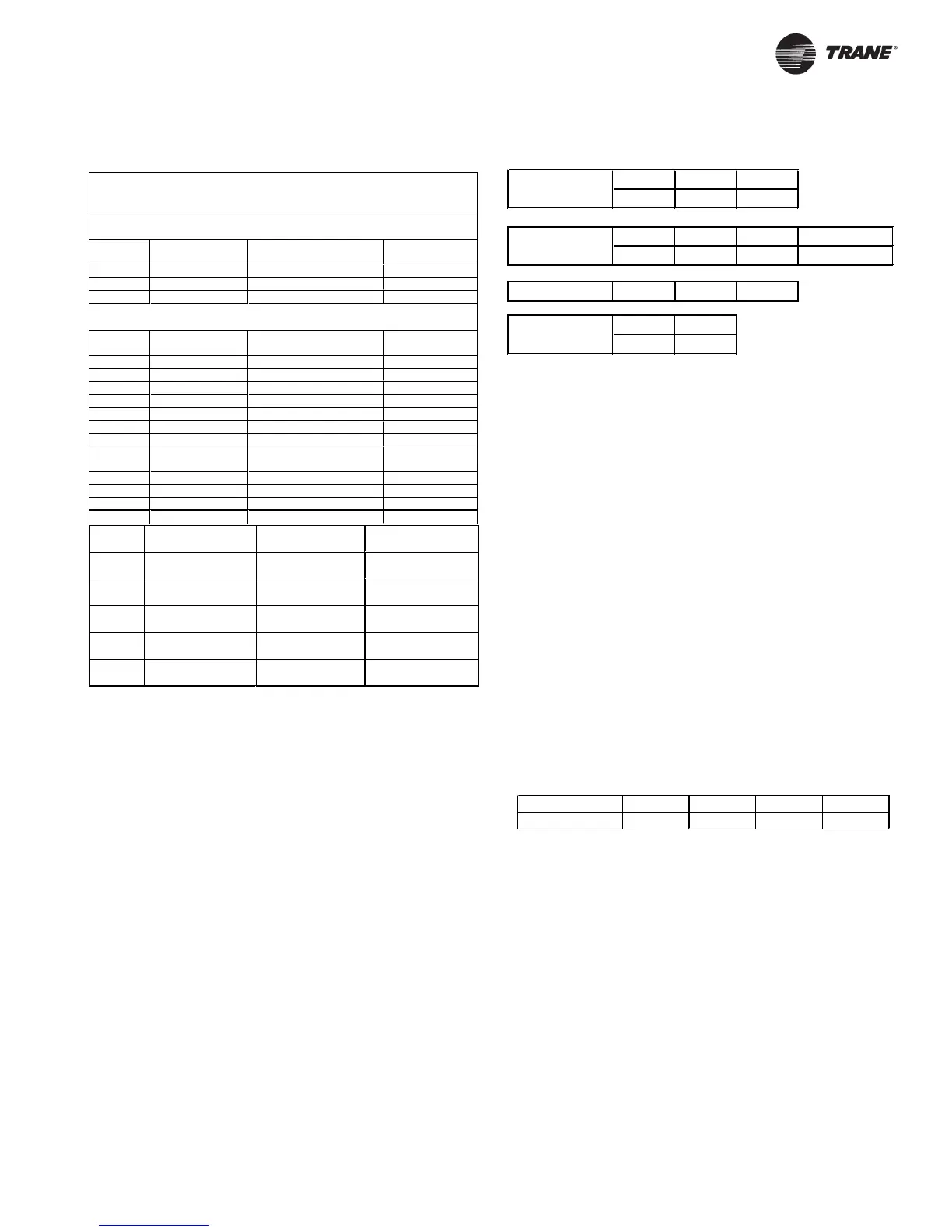
The table below specifies fuses used internally in the TR1 series
drives. Use the specified fuse or an exact replacement only.
Internal Fuses Provided with TR1 Series VFDs
200 – 240 VAC
TR1 Type Soft Charge Fuse
(3X)
Soft Charge Resistor
Fuse (1X)
Power Card
Fuse (1X)
6042 Littelfuse KLK-15 Littelfuse KLK-D-12 Bussmann KTK-5
6052 Littelfuse KLK-15 Littelfuse KLK-D-12 Bussmann KTK-5
6062 Littelfuse KLK-15 Littelfuse KLK-D-12 Bussmann KTK-5
380 – 460 VAC
TR1 Type Soft Charge
Fuse (3X)
Soft Charge Resistor
Fuse (1X or 2X)
Power Card
Fuse (1X)
6072 Littelfuse KLK-15 Littelfuse KLK-D-12 (1X) Bussmann KTK-5
6102 Littelfuse KLK-15 Littelfuse KLK-D-12 (1X) Bussmann KTK-5
6122 Littelfuse KLK-15 Littelfuse KLK-D-12 (1X) Bussmann KTK-5
6150 Littelfuse KLK-30 Littelfuse KLK-D-12 (1X) Bussmann KTK-5
6175 Littelfuse KLK-30 Littelfuse KLK-D-12 (2X) Bussmann KTK-5
6225 Littelfuse KLK-30 Littelfuse KLK-D-12 (2X) Bussmann KTK-5
6275 Littelfuse KLK-30 Littelfuse KLK-D-12 (2X) Bussmann KTK-5
TR1 Type Soft Charge
Fuse (3X)
Line Snubber
Fuse (3X)
Interface Board
Fuse (1X)
6350 Littelfuse KLK-9 Littelfuse KLK-15 Bussmann KTK-5
6400 Littelfuse KLK-9 Littelfuse KLK-15 Bussmann KTK-5
6500 Littelfuse KLK-9 Littelfuse KLK-15 Bussmann KTK-5
6550 Littelfuse KLK-9 Littelfuse KLK-15 Bussmann KTK-5
Terminal Identification
The connectors for input and output power, auxiliary relay connections,
and external DC bus are identified in the tables below.
CAUTION
Drive Failure!
Do not connect input power to drive output
motor terminals. Connecting input power to
motor terminals will result in drive failure when
power is applied.
On drives with an auxiliary enclosure, some or all of the power
connections at the drive will be factory made. Custom input and output
terminals may be inside the auxiliary enclosure. See the drawings
supplied with the drive for details on custom terminal blocks and conduit
entry locations for the auxiliary enclosure.
Input Power Delay
To ensure that the input surge suppression circuitry performs correctly,
a time delay between successive applications of input power must be
observed.
The table below shows the minimum time that must be allowed between
applications of input power.
L1 L2 L3
91 92 93
AC Line
U V W PE (ground)
96 97 98 99
Motor
(-) DC (+) DC
88 89
DC Bus
AUX RELAY 01 02 03
Input voltage 380 V 415 V 460 V 600 V
W aiting time 48 sec 65 sec 89 sec 133 sec
TR1 Type
Soft Charge
Fuse (3 phase)
Fan Fuse
(1 phase)
Power Card/SMPS
Fuse (1 phase)
6152 Bussmann
FWH20A6F
Bussmann KTK-4 Bussmann KTK-4
6172 Bussmann
FWH20A6F
Bussmann KTK-4 Bussmann KTK-4
6222 Bussmann
FWH20A6F
Bussmann KTK-4 Bussmann KTK-4
6272 Bussmann
FWH20A6F
Bussmann KTK-4 Bussmann KTK-4
6352 Bussmann
FWH20A6F
Bussmann KTK-4 Bussmann KTK-4