BAS-SVN032B-EN
7
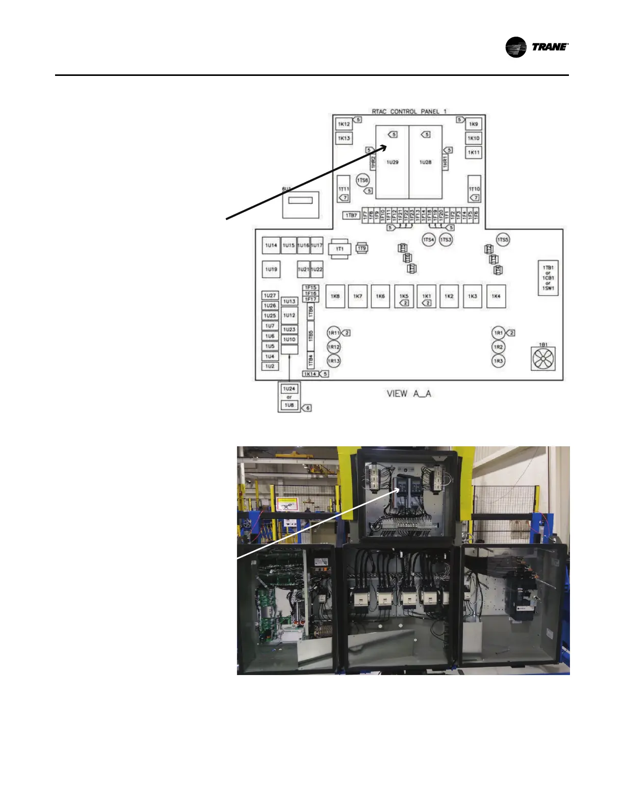
Figure 1. RTAC Panel Configuration
Low Ambient Option
Condenser Fan VFD
Figure 2. Typical RTAC 200 ton panel illustration and low ambient option VFD location
Low Ambient Option
Condenser Fan VFD
6. Disconnect power supply wires from VFD connection points 91, 92, 93, 95 (L1, L2, L3, GND
respectively).
7. Disconnect output power wires from VFD connection points 96, 97, 98, 99 (T1, T2, T3, GND
respectively).
8. Disconnect all control wires from the TR1 VFD itself and note the connection point numbers.
RReemmoovviinngg tthhee EExxiissttiinngg VVFFDD aanndd CCoommppoonneennttss