8
BAS-SVN032B-EN
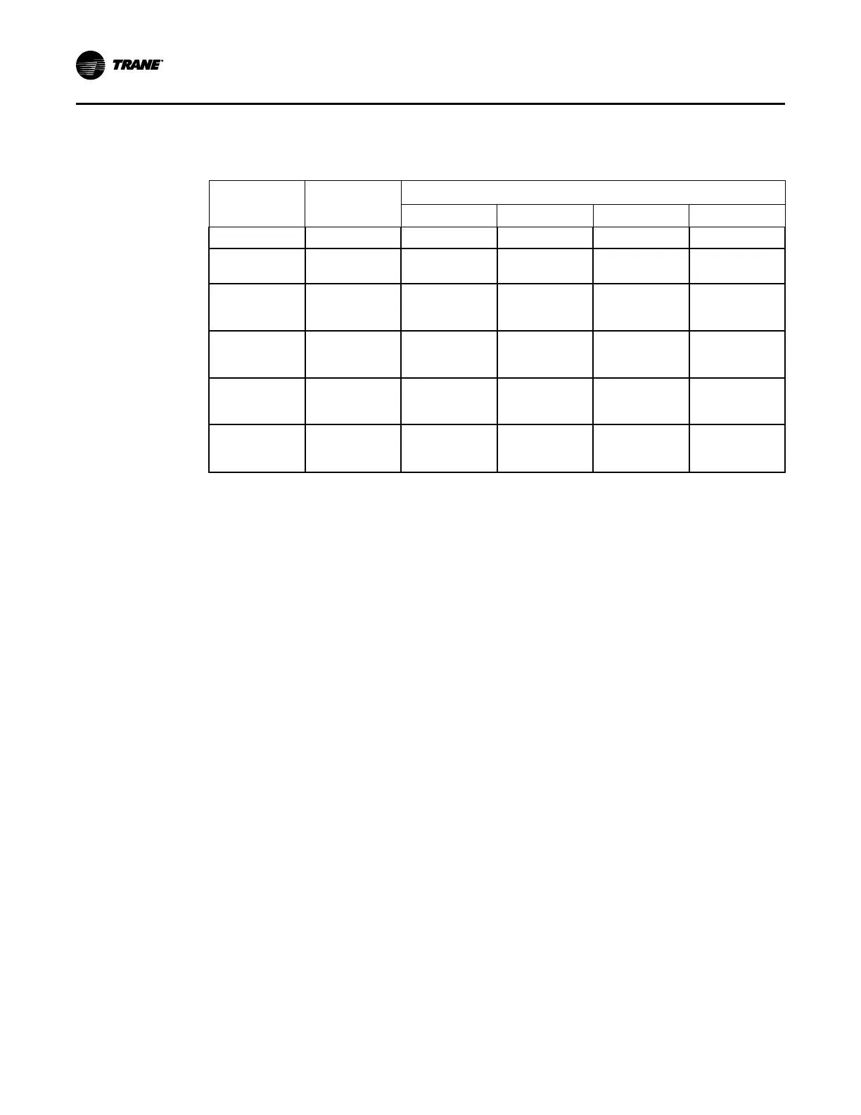
The TR1 and TR170 have the same connection point numbers. See the following table for
common control wiring and their connection point numbers
Table 2. Typical Control Wires
Drive
Connection
Description
Drive Designator
1U28 1U29 2U28 2U29
12 +24 VDC 151A 151B 651A 651B
18 Digital Input
(RUN)
152A 152B 652A 652B
53 Analog Input 0-
10 (Speed
Command)
119A 122A 122A
(a)
or
619A
(b)
622A
55 Common 128A 129A 129A
(a)
or
628A
(b)
629A
1 Relay 1 [0]
Common
121A 123A 123A
(a)
or
620A
(b)
623A
3 Relay 1 [0]
Normally Closed
(Alarm)
120A 124A 124A
(a)
or
621A
(b)
624A
(a)
Two-cpmpressor applications
(b)
Three and four-compressor applications
9. The blanket heater used with the Trane TR1 drive is sized incorrectly for use with a Trane
TR170 drive. Disconnect the heater wires at 1TB7-3,4 or 2TB7-3,4.
10. Locate and remove the four (4) fasteners securing the TR1 drive to its back panel after all
cables and power supply wiring have been disconnected.
11. Remove existing drive and heater blanket.
RReemmoovviinngg tthhee EExxiissttiinngg VVFFDD aanndd CCoommppoonneennttss