©2020 Trane
Trane has a policy of continuous product and product data improvement and reserves the
right to change design and specifications without notice. We are committed to using
environmentally conscious print practices.
Trane - by Trane Technologies (NYSE: TT), a global climate innovator - creates
comfortable, energy efficient indoor environments for commercial and residential
applications. For more information, please visit trane.com or tranetechnologies.com.
6
7
BAS-SVN099E-EN 11 Jun 2020
Supersedes X39641254-01D (Mar 2017)
Wiring AC Power
1. Connect both secondary wires from the 24 Vac transformer to the XFMR terminals on the
device.
2. Ensure the device is properly grounded.
Important: This device must be grounded for proper operation! The factory-supplied ground
wire must be connected from any chassis ground connection on the device to an appropriate
earth ground ( ). The chassis ground connection used may be the 24 Vac transformer input
at the device, or any other chassis ground connection on the device.
Note: The device is not grounded through the DIN rail connection.
Startup and Power Check
1. Verify that the 24 Vac connector and the chassis ground are properly wired.
2. Each device must have a unique and valid address. The address is set either by using the rotary
address switches or, for Tracer SC applications, by using the Software Set Device ID function
in the Tracer TU service tool. Valid addresses are 001 through 127 for Tracer SC applications.
Important: A duplicate address or a 000 address will cause communication problems in
a BACnet link: The Tracer SC will not discover all devices on the link and the
installation process will fail after discovery.
3. Remove the lockout/tagout from the line voltage power to the electrical cabinet.
4. Apply power to the UC400 and observe the power check sequence that follows:
The power LED lights red for 1 second. Then it changes to green, indicating that the unit is
properly booted and ready for application code. Flashing red indicates that a fault conditions
exists. The Tracer TU service tool can be used to check for fault conditions after application
code and TGP2 programming have been loaded.
Input/Output Wiring
Pre-power checks of input/output devices should be performed according to the Tracer UC400 IOM
(BAS-SVX20). Maximum wire lengths are as follows:
NOTICE
Equipment Damage!
Remove power to the UC400 before making input/output connections. Failure to do so may cause
damage to the controller, power transformer, or input/output devices due to inadvertent
connections to power circuits.
Maximum Wire Lengths
Pre-power checks of input/output devices should be performed according to the Tracer
UC400 IOM (BAS-SVX20). Maximum wire lengths below.
Type Inputs Outputs
Binary 1,000 ft (300 m) 1,000 ft (300 m)
0–20 mA 1,000 ft (300 m) 1,000 ft (300 m)
0–10 Vdc 300 ft (100 m) 300 ft (100 m)
Thermistor/Resistive 300 ft (100 m) Not Applicable
• All wiring must be in accordance with the NEC and local codes.
• Use only 18–22 AWG (1.02 mm to 0.65 mm diameter), stranded, tinned-copper, shielded, twisted-
pair wire.
• Analog and 24 Vdc output wiring distances are dependent on the receiving unit specifications.
•DO
NOT run input/output wires or communication wires in the same wire bundle with AC power
wires.
Note: A pigtail connection should be
used between the chassis ground on the
device and an earth ground, if the device
is not grounded through one leg of the
transformer wiring.
Rotary
Address
Switches
24 Vac
Transformer
Marquee LED
Tug Test for Terminal Connectors
If using terminal connectors for wiring the UC400, strip the wires to expose 0.28 in (7 mm) of bare wire.
Insert each wire into a terminal connector and tighten the terminal screws. A tug test is recommended after
tightening terminal screws to ensure that all wires are secure. Torque reference: Tighten screw terminals
to 0.5–0.6 N·m (71–85 ozf/in or 4.4–5.3 lbf/in)
Note: N·m=Newton meter • ozf/in= ounce force per inch • lbf/in= pound force per inch
BACnet MS/TP Link Wiring
BACnet MS/TP link wiring must be field-supplied and installed in compliance with NEC and local codes. In
addition, the wire must be the following type: low capacitance, 18 gauge, stranded, tinned copper, shielded,
twisted pair. for more details, refer to the wiring guide for the Unit Controller Wiring for Tracer SC System
Controller, BAS-SVN03.
Important: Polarity must be maintained between all devices on the link.
Factory Defaults
The controller is shipped with the following default settings. To change defaults, use the Tracer TU service
tool or a BAS, as appropriate.
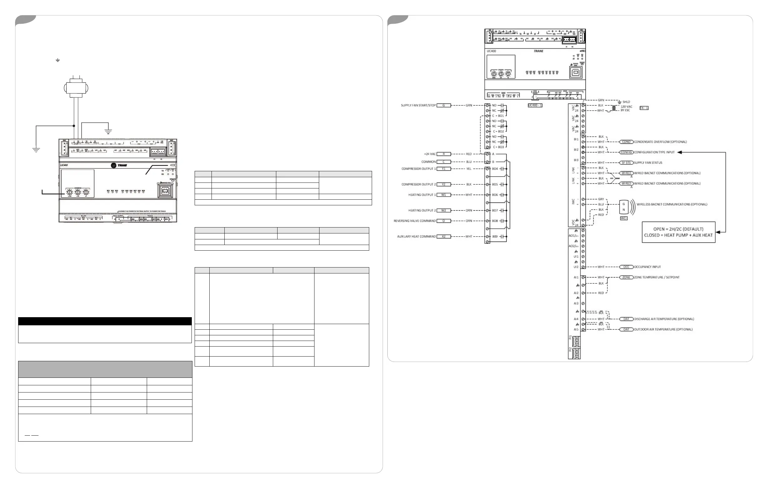
• Equipment Type: The Tracer UC400 ships from the factory configured to control a 2-heat/2-cool
rooftop unit. To change this configuration, refer to Table 2 below.
• Setpoints: In occupied mode, the controller can receive a setpoint from either a zone sensor or from
a BAS (default). The following are the default setpoints:
• Heating: 69.0°F (21.7°C)
• Cooling: 74.0°F (23.3°C)
In unoccupied mode, the controller will operate at:
• Heating: 66.0°F (15.6°C)
• Cooling: 78.0°F (29.4°C)
• Inputs and Outputs: Refer to the following tables for individual input and output factory defaults.
Table 1. Analog Inputs
Label Functions Defaults Rating
AI1 Zone Temperature Zone Temperature
10 k@ 77°F (25°C)AI4 Discharge Air Temp Discharge Air Temp
AI5 Outdoor Air Temp Outdoor Air Temp
AI2 Temperature Setpoint Zone Temp Setpoint 1 k potentiometer
Note: For best results and accuracy, use only Trane temperature sensors.
Table 2. Binary Inputs
Label Functions Defaults Rating
BI1 Occupancy
Occupancy
Volt-free Dry Contact
BI2 Heat Pump Selection Input
Note: Do not apply power to these inputs. Connect jumper to BI2 for heat pump application.
Table 3. Binary Outputs
Label 2H/2C Heat Pump Rating
BO1 BO1 Supply Fan
• 10 A; up to 277 Vac
•1/3 hp @ 125 Vac OR
1/2 hp @ 277
• 2 A; up to 125 Vac
• 8 A; up to 250 Vac OR
10 A; up to 30 Vac OR
10 A; up to 30 Vdc
BO4 Cool stage 1 (Y
1
) Compressor 1(Y
1
)
0.5 A - 12 VA@ 24 VAC
(UC400 BO4 Rating)
BO5 Cool stage 2 (Y
2
) Compressor 2 (Y
2
)
BO6 Heat stage 1 (W
1
)Not Used
BO7 Heat stage 2 (W
2
)Not used
BO8 Not Used
Reversing Valve
Output
BO9 Not Used
Auxiliary Heat
Command
Agency Listings and Compliance
The European Union (EU) Declaration of Conformity is
available from your local Trane
®
office.

 Loading...


