EasyManua.ls Logo

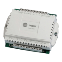
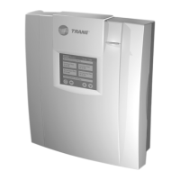
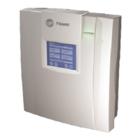
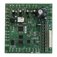
Trane Tracer ZN524 - User Manual

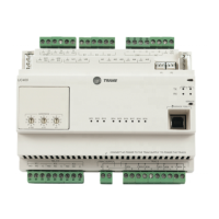
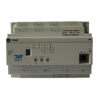
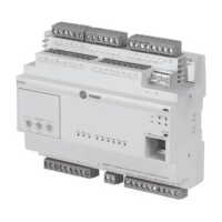
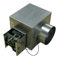
Trane Tracer ZN524
52 pages
Print Icon
To Next Page IconTo Next Page
Loading...
Installation
Owner
Diagnostics
Tracer
®
ZN524 for
water-source heat pumps
Order No: CNT-SVX11A-EN Date: August 2003
CNT-SVX11A-EN

Questions and Answers

  • T
    Tina JenkinsAug 20, 2025
    What to do if my Trane Tracer ZN524 Controller shows a Low Air Flow—Fan Failure diagnostic?
    • B
      brooksangelaAug 20, 2025
      This indicates that a fan status device is present and fails to close after 1 minute of unit start-up, or it opens for more than 1 minute during normal unit operation.
  • A
    Andrew ThomasAug 22, 2025
    What happens if my Trane Tracer ZN524 displays 'Maintenance Required'?
    • D
      Deborah MillerAug 22, 2025
      This indicates that the fan run-time exceeds the configurable limit.
  • M
    Marie StewartAug 25, 2025
    What to do if my Trane Tracer ZN524 displays 'Invalid Unit Configuration'?
    • M
      Michael BoydAug 25, 2025
      To correct this problem, the unit must be re-configured with a valid configuration.
  • C
    Christine LarsonAug 26, 2025
    What to do if my Trane Tracer ZN524 Controller's outside air damper stays closed?
    • S
      Sophia RamirezAug 26, 2025
      Ensure the wiring between the controller outputs and the outdoor air damper is present and correct for normal damper operation.
  • A
    Ashley RodriguezAug 28, 2025
    What does it mean if the red LED is continuously on in my Trane Tracer ZN524 Controller?
    • N
      Nicholas PayneAug 28, 2025
      This could mean someone is pressing the Service push button or the controller has failed.
  • P
    Paula ThompsonAug 29, 2025
    What does it mean if my Trane Tracer ZN524 Controller has a Space Temperature Failure?
    • T
      theresabryantAug 29, 2025
      This happens if the Tracer ZN524 has validated a space temperature input and then the input becomes invalid.
  • A
    andrew84Aug 31, 2025
    What does it mean if my Trane Tracer ZN524 has an Outdoor Air Temperature Failure?
    • Z
      zblairSep 1, 2025
      This occurs if the Tracer ZN524 has validated an outdoor air temperature input and then the input becomes invalid.
  • S
    sriveraSep 2, 2025
    What does it mean if my Trane Tracer ZN524 has a Generic Temperature Failure?
    • K
      Kyle JacksonSep 2, 2025
      This indicates that the Tracer ZN524 has validated a generic temperature input and then the input becomes invalid.
  • W
    William HollowaySep 4, 2025
    What does it mean if my Trane Controller has a Humidity Input Failure?
    • J
      Jason NavarroSep 4, 2025
      This indicates that the Tracer ZN524 has validated a relative humidity input and then the input becomes invalid.
  • B
    Brian HinesSep 6, 2025
    What does it mean if my Trane Tracer ZN524 has a CO2 Sensor Failure?
    • K
      katiearroyoSep 6, 2025
      This indicates that the Tracer ZN524 has validated a CO2 input and then the input becomes invalid.

Summary

Communication Configurations

Integrated Comfort System (ICS)

Explains ICS setup with Tracer Summit and limits.

Peer-to-Peer Communications

Details how units share data without a central system.

Communication Interface and Modes

Binary Input and Output Configuration

Binary Input Details

Explains binary inputs and their functions for the J2 terminal board.

Binary Output Details

Lists binary outputs, their functions, and ranges for the J1 terminal board.

Analog Input Configuration

Wiring and Power Connections

Typical Wiring Diagrams

Wiring Diagrams for Specific Options

Unit Configuration and Applications

Configuration Parameters: Fan and Setpoints

Unit Operation Modes

Operational Modes and Functions

Advanced Unit Operations and Protections

Electric Heat, DX Cooling, and Water Valves

Special Operating Modes

Troubleshooting Overview and Indicators

Safety and LED Status Indicators

Covers safety warnings and the meaning of Red, Green, and Yellow LEDs.

Service Buttons and Manual Output Test

Explains the service push button and manual output test procedure.

Manual Output Test Procedure

Troubleshooting Diagnostics

Common Sensor and Input Diagnostics

Explains failure diagnostics for sensors like temp, CO2, humidity, and EWT.

Unit Configuration and Maintenance Diagnostics

Covers diagnostics for invalid configuration, maintenance alerts, and defrost lockout.

Unit Controller Diagnostic Table

Diagnostics: Pressure, Airflow, and Temperature

Lists diagnostics related to pressure, airflow, and temperature failures.

Diagnostics: Discharge Air, Outdoor Air, Humidity

Lists diagnostics for discharge air, outdoor air, and humidity input failures.

Unit Controller Diagnostics Continued

Diagnostics: Humidity, CO2, Generic Air, Maintenance

Lists diagnostics for humidity, CO2, generic air, and maintenance required.

Diagnostics: Fan Mode, Setpoint, Configuration

Lists diagnostics for fan mode, setpoint, and invalid unit configuration.

Managing and Resetting Diagnostics

Diagnostic Handling and Reset Methods

Explains how to interpret multiple diagnostics and reset methods.

Automatic Diagnostic Reset Scenarios

Details automatic resets via power cycling, fan switch, BAS, and Rover.

Fan Troubleshooting

Fan Output Troubleshooting Causes

Lists common causes for fan outputs not energizing.

Fan Operation Issues

Explains various reasons why fans might not operate correctly.

Valve Troubleshooting

Isolation Valves Stay Closed

Identifies causes for isolation valves remaining closed.

Isolation Valves Stay Open

Identifies causes for isolation valves remaining open.

DX;Electric Heat and Damper Troubleshooting

Compressor;Electric Heat Output Issues

Lists causes for compressor or electric heat outputs not energizing.

Outside Air Damper Closed Issues

Explains why the outside air damper might stay closed.

Damper and Sensor Troubleshooting

Outside Air Damper Open Issues

Explains reasons for the outside air damper staying open.

Entering Water Temperature Sensor Errors

Lists causes for read-out errors from the EWT sensor.

Circuit Board Replacement Procedure

Safety Precautions for Replacement

Emphasizes safety steps before replacing the circuit board.

Step-by-Step Replacement Guide

Provides instructions for replacing the ZN524 controller circuit board.

Trane Tracer ZN524 Specifications

General IconGeneral
TypeZone Controller
Communication ProtocolBACnet MS/TP
Input Voltage24 VAC
Enclosure RatingNEMA 1
Operating Temperature Range32°F to 122°F (0°C to 50°C)
MemoryNon-volatile

Related product manuals