12 CNT-SVX11A-EN
Installation & Wiring
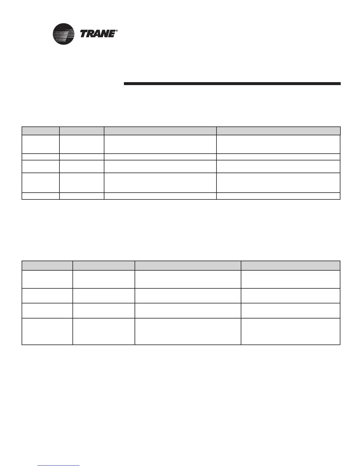
Description Terminals Function Range
Zone TB3-1 Space temperature input 5× to 122×F
(-15× to 50×C)
Ground TB3-2 Analog ground NA
Set TB3-3 Local setpoint input 40× to 115×F
(4.4× to 46.1×C)
Fan TB3-4 Fan switch input 4821 to 4919 V (Off)
2297 to 2342 V (Auto)
15137 to 16463 V (High)
Ground TB3-6 Analog ground NA
Analog Inputs
Table 3: Analog Inputs (Zone Sensor)
Analog input Terminal Function Range
AI 1 J3 - 1 Entering water temperature or -40 to 212
0
F (-40
0
to 100
0
C)
J3 - 2 outside air temperature -40 to 212
0
F (-40
0
to 100
0
C)
AI 2 J3 - 3 Discharge air temperature -40 to 212
0
F (-40
0
to 100
0
C)
J3 - 4
AI 3 J3 - 5 Leaving water temperature -40 to 212
0
F (-40
0
to 100
0
C)
J3 - 6
AI 4 J3 - 7 Universal 4-20mA input 4-20ma
J3 - 8 Humidity 0-100%
J3 - 9 CO
2
0 - 2000 ppm
Table 4: Analog Inputs with terminal connections
1,2
1. Trane Rover service tool uses the unit type to help determine and download the proper default analog input configuration.
2. Analog input 3 (AI 3) configured as generic temperature input does not affect unit operation. When configured, the Tracer
TM
ZN524 unit con-
troller communicates the generic temperature value to Rover or Tracer Summit and displays it as generic temperature.

 Loading...


