CNT-SVX11A-EN 13
Installation & Wiring
Mounting
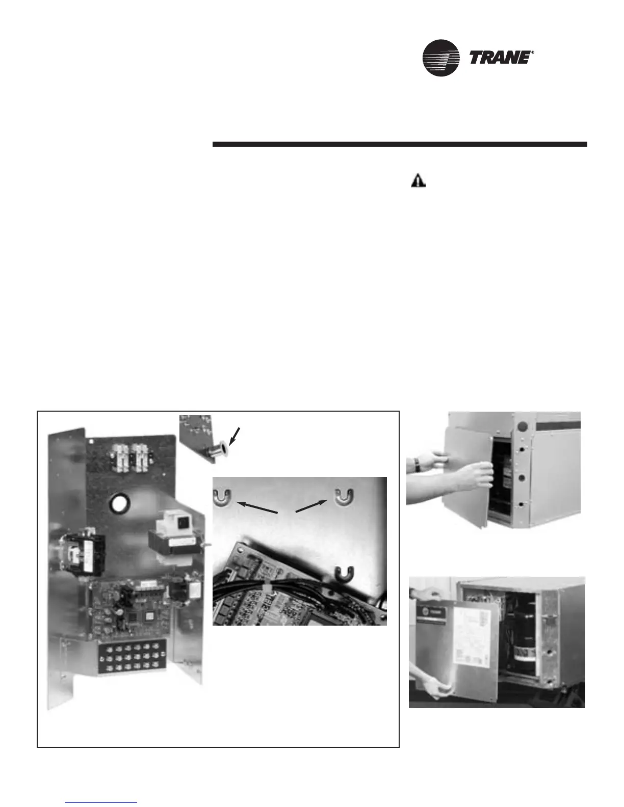
The Tracer ZN524 circuit board is locat-
ed in the control box, which is mounted
behind the front panel of the water-
source heat pump (See Figures 9 and
10 for more information). The sheet
metal mounting plate has raised
embosses to accept the mounting feet
on the circuit board. (See Figure 8: For
close-up of horseshoe embosses and
circuit board mounting feet.) This
design allows the Tracer ZN524 con-
troller to be secured with a minimal
number of sheet metal screws
.
The mounting position on the vertical
water-source heat pump allows com-
plete access to the Tracer ZN524 by
removing the front panel - six screws
total. (See Figure 9) Removing the
screws and panel allows access to the
components of the control board.
The mounting plate on both the hori-
zontal and vertical water-source heat
pumps allow complete access to the
Tracer ZN524 by removing the front
panel - also six screws total. (See
Figure 10) Removing the screws and
panel allows access to the components
of the control board.
For additional convenience, quick con-
nects and modular wire harnesses are
used on the control board and mount-
ing plate. These quick connects help
facilitate ease of wiring devices (e.g.,
zone sensor) to the control board, and
helps add accessibility to major compo-
nents.
WARNING
Hazardous Voltage!
Disconnect all electric power, including
remote disconnects before servicing.
Follow proper lockout/tagout proce-
dures to ensure the power can not be
inadvertently energized. Failure to dis-
connect power before servicing could
result in death or serious injury.
Figure 8: A) Cut-away view of the
ZN524 control mounted on the control
box panel. B) Close-up of mounting
shoe on backside of control which slide
into the horseshoe brackets (C) on the
control panel.
Figure 9: Removing front panel of verti-
cal unit to access control panel.
Figure 10: Removing front panel of
horizontal unit to access control panel.
A
C
B

 Loading...


