14 CNT-SVX11A-EN
Installation & Wiring
Wiring
Live Electrical Components!
During installation, testing, servicing,
and troubleshooting of this product, it
may be necessary to work with live
electrical components. Have a qualified
licensed electrician or other individual
who has been properly trained in han-
dling live electrical components per-
form these tasks. Failure to follow all
electrical safety precautions when
exposed to live electrical components
could result in death or serious injury.
Use Copper Conductors Only!
Unit terminals are not designed to
accept other types of conductors.
Failure to use copper conductors may
result in equipment damage.
Important! All wiring must comply
with state, local, and federal
guidelines. Contact the appropriate
local agency for further
information.
Important! Wires for temperature
sensors, communication lines, 24
VAC, and contact closure sensing
inputs should not be bundled with
or run near high voltage wiring.
• To prevent damage to the unit, refer to
the diagram provided on the unit’s
inside access panel for specific wiring
information. Most control components
are factory-wired. Zone sensors and
communication wiring is to be
installed by the contractor.
• Power wiring must be separated from
the Tracer ZN524 and all low voltage
wires. External input wires should be
run in separate conduits from high
voltage wires.
• Wires connected to pin headers
should be formed and routed so as to
cause minimum strain on the Tracer
ZN524 connector.
• A minimum of 1.5" clearance (from the
pin centerline) for wires up to 16 AWG
is recommended for bending and
forming wires.
• All sensor and input circuits are at or
near ground potential. Do not connect
any sensor or input circuit to an
external ground connection.
• A close-coupled ground connection is
required for the Tracer ZN524.
• Table 5: Tracer ZN524 Wiring
Requirements, shows Tracer ZN524
wire types and lengths.
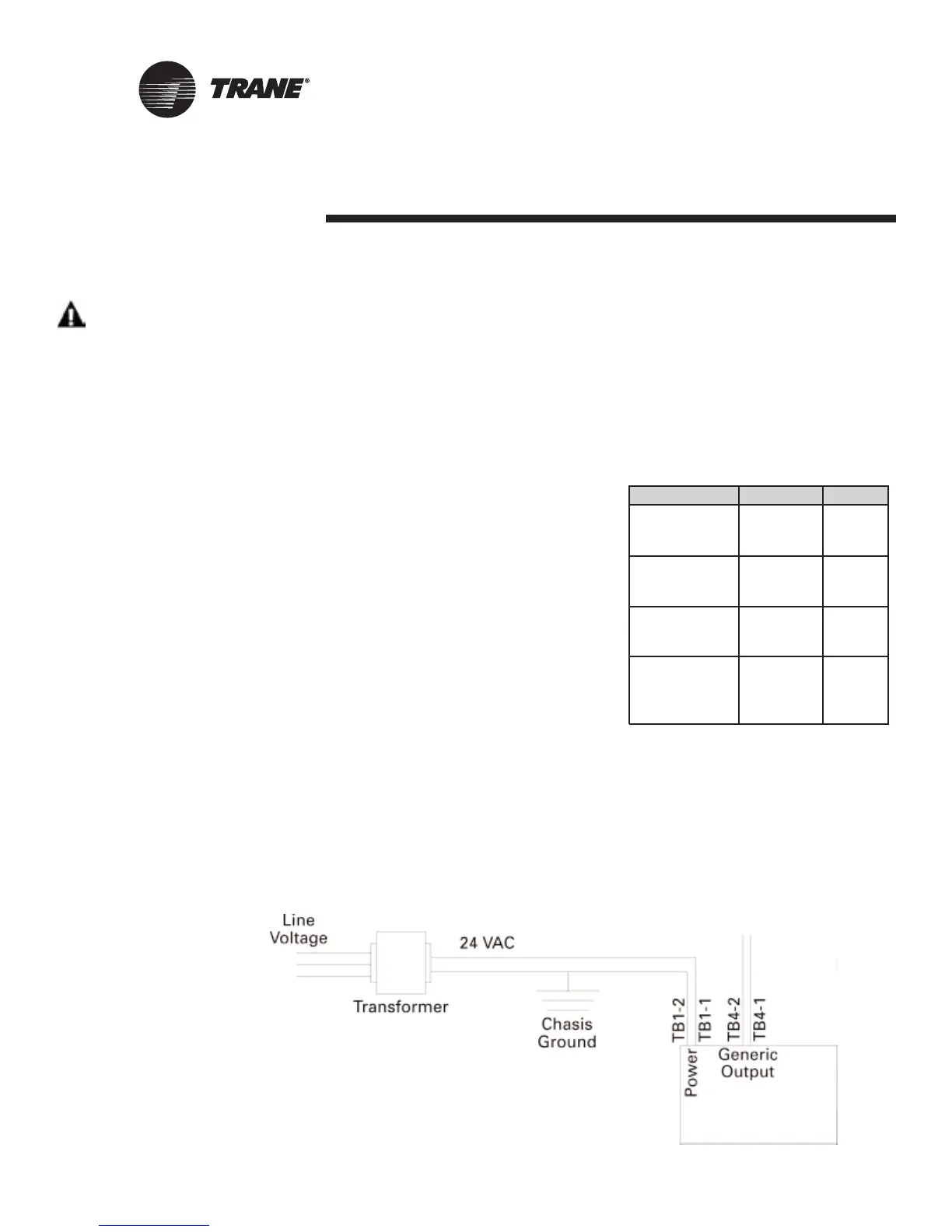
Power
The Tracer ZN524 controller is powered
by 24 VAC. (See Table 5: “Tracer ZN524
wiring requirements”)A total of two 1/4-
inch quick-connect terminals are provid-
ed for 24 VAC connection to the board.
Figure 10: Power connections to the Tracer ZN524 unit controller
Application Wire Type Length
Contact 18 AWG Up to
Closure 1000 ft.
24 VAC 16-22 AWG Up to
1000 ft.
Zone 16-22 AWG Up to
Sensor 200 ft.
Communications Belden 8760 Up to
or 5000 ft.
equivalent
ZN524
WARNING
CAUTION
Table 5:Tracer ZN524 wiring
requirements

 Loading...


